Top Flite TOPA0708 User Manual
Page 16
16
❏
18. Slide a 3.5mm wheel collar followed by the tail
wheel and a second wheel collar on the tail gear wire.
Apply a drop of threadlocker to the threads of the 2.5
x 4mm machine screws. Secure the wheel collar on
the tail gear wire with the machine screws. Make sure
the screw in the outer wheel collar is tightened on the
fl at spot.
INSTALL THE ENGINE
❏
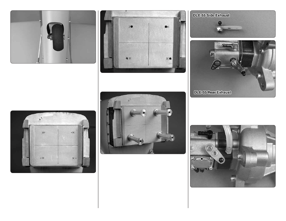
1. The fi rewall has two sets of engine mounting bolt
patterns embossed on it. The “+” are for the DLE-55
Rear Exhaust gas engine and the “X” are for the DA-50,
DLE-55 Side Exhaust, and O.S. GT55 gas engines. If
you are installing an engine with a different mounting
bolt pattern the fi rewall also has crosshairs embossed
on it to help locate the correct mounting location.
❏
2. Drill a 13/64" [5mm] hole through the fi rewall at
each of the appropriate locations marked with an “X”
or “+”.
❏
3. Insert four 10-32 x 1-1/2" [38mm] socket head cap
screws, #10 lock washers and #10 Fender washers (not
included) through the holes from the backside of the
fi rewall. Apply a drop of threadlocker to the threads of
each screw. Thread the engine standoffs onto the screws
and tighten them against the fi rewall. For a reference,
once the engine is installed, the front of the engine drive
washer should be approximately 6-3/4" (171mm) from
the front of the fi rewall.
❏
4. If installing the DLE-55 Side Exhaust engine, install
a 2-56 ball link ball on the throttle arm extension and
secure it with a 2-56 nylon locknut. If installing the DLE-
55 Rear Exhaust engine, install a 2-56 ball link ball on
the throttle arm and secure it with a 2-56 nylon locknut.
❏
5. On the DLE-55 Side Exhaust engine, use the
screw and nut supplied with the throttle arm extension.
Attach the extension to the throttle arm. Again, use
threadlocker on the threads.