Top Flite TOPA0965 User Manual
Page 28
28
These are the recommended
control surface throws:
LOW RATE
ELEVATOR: 1/2" [13mm], 8° up
1/2" [13mm], 8° down
RUDDER:
1-1/4" [32mm], 15° left
1-1/4" [32mm], 15° right
AILERONS: 3/4" [19mm], 19° up
3/4" [19mm], 19° down
FLAPS:
1" [25mm], 26° up
1" [25mm], 26° down
HIGH RATE
ELEVATOR: 5/8" [16mm], 11° up
5/8" [16mm], 11° down
RUDDER:
1-3/4" [44mm], 22° left
1-3/4" [44mm], 22° right
AILERONS: 1" [25mm], 26° up
1" [25mm], 26° down
FLAPS:
1-3/8" [35mm], 38° up
1-3/8" [35mm], 38° down
Note: When fl aps are deployed you can expect
the airplane to balloon slightly. To minimize this we
mixed 1/32" [0.8mm] down elevator trim when the
fl aps were deployed. If you have a fl ap to elevator
mix you may wish to consider this mix as well.
BALANCE THE MODEL (C.G.
)
More than any other factor, the C.G. (balance point)
can have the greatest effect on how a model fl ies,
and may determine whether or not your fi rst fl ight
will be successful. If you value this model and wish
to enjoy it for many fl ights, DO NOT OVERLOOK
THIS IMPORTANT PROCEDURE. A model that
is not properly balanced will be unstable and
possibly unfl yable.
At this stage the model should be in ready-to-fl y
condition with all of the systems in place including
the engine, landing gear, covering and paint, and the
radio system.
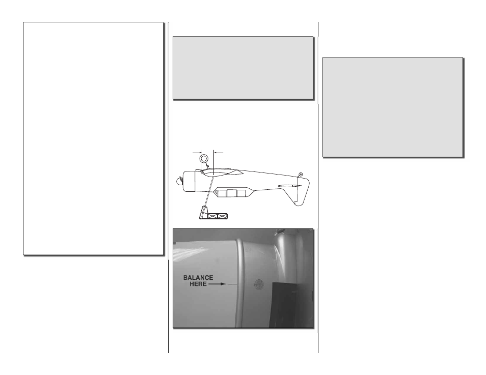
4-1/4" [108mm]
❏
1. Use a felt-tip pen or 1/8" [3mm]-wide tape to
accurately mark the C.G. on the top of the wing on
both sides of the fuselage. The model should be
balanced up-side down. The C.G. is located 4-1/4"
[108mm] back from the leading edge of the bottom
wing, measured where the center section of the wing
and the outer wing panel join.
This is where your model should balance for the
fi rst fl ights. Later, you may wish to experiment by
shifting the C.G. up to 1/4" [6mm] forward or 1/4"
[6mm] back to change the fl ying characteristics.
Moving the C.G. forward may improve the
smoothness and stability, but the model may then
require more speed for takeoff and make it more
diffi cult to slow for landing. Moving the C.G. aft
makes the model more maneuverable, but could
also cause it to become too diffi cult to control. In
any case, start at the recommended balance
point and do not at any time balance the model
outside the specifi ed range.
❏
2. With the wing attached to the fuselage, all parts
of the model installed (ready to fl y) and an empty
fuel tank, place the model upside-down on a Great
Planes CG Machine, or lift it upside-down at the
balance point you marked.
❏
3. If the tail drops, the model is “tail heavy” and the
battery pack and/or receiver must be shifted forward
or weight must be added to the nose to balance. If the
nose drops, the model is “nose heavy” and the battery
pack and/or receiver must be shifted aft or weight must
be added to the tail to balance. If possible, relocate
the battery pack and receiver to minimize or eliminate
any additional ballast required. If additional weight is
required, nose weight may be easily added by using
Great Planes (GPMQ4485) “stick-on” lead. A good
place to add stick-on nose weight is to the fi rewall
(don’t attach weight to the cowl—it is not intended
to support weight). Begin by placing incrementally
increasing amounts of weight on the bottom of the
fuse over the fi rewall until the model balances. Once
you have determined the amount of weight required,
it can be permanently attached. If required, tail weight
may be added by cutting open the bottom of the fuse
and gluing it permanently inside.