Top Flite TOPA0965 User Manual
Page 18
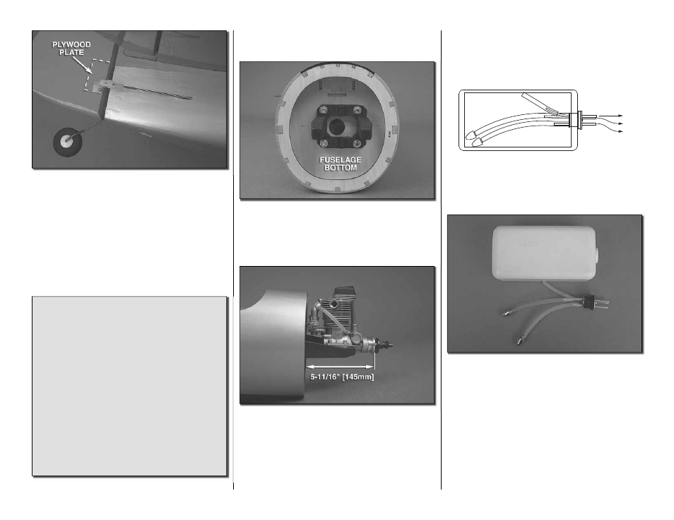
18
❏
21. Screw a nylon clevis onto a .074 x 36" [914mm]
threaded wire 20 turns. Slide a nylon clevis retainer
onto the clevis. Install the clevis into the outer hole
of the control horn. Then slide the silicone retainer
over the clevis. Mark the location for the control horn
onto the rudder. Drill a 1/16" [1.6mm] holes into the
plywood plate in the rudder. Do not drill through the
rudder. Secure the horn to the rudder with #2 x 3/8"
[10mm] screws.
Did you know…The AT-6 Texan became the
classroom for the majority of the Allied pilots who
fl ew in World War II, and trained several hundred
thousand pilots in 34 different countries. Its basic
design was as a trainer, with the characteristics
of a high speed fi ghter, and was well suited to the
intermediary task of training pilots before letting
them loose in an actual fi ghter aircraft. Although
not as fast as a fi ghter, it was easy to maintain and
repair, had more maneuverability and was easier to
handle. A pilot’s airplane, it could roll, Immelmann,
loop, spin, snap, and vertical roll. It was used to
train pilots in all aspects of tactical operations, such
as dog-fi ghting, ground strafi ng, carrier landings,
and bombardment. It also included the capacity for
fi xed and fl exible guns, cameras, and just about
any other device that the military required.
INSTALL THE ENGINE FUEL TANK
AND THROTTLE SERVO
❏
1. Bolt the engine mount to the fi rewall with four
8-32 x 1" [25mm] socket head cap screw, #8 lock
washer and #8 fl at washer. Place your engine on the
mount and adjust the mounting rail position to match.
Then tighten the bolts.
❏
2. Position the engine on the mount so the distance
from the fi rewall to the front of the thrust washer
measures 5-11/16" [145mm]. Mark the location of
the engine on the mount. The Great Planes
®
“Dead
Center” Hole Locator (GPMR8130) works well for
this. Drill through the marks you have made with a
#29 or 9/64" [3.6mm] drill bit. Tap each hole with an
8-32 tap.
❏
3. Install the engine to the mount with four each,
8-32 x 1" [25mm] socket head cap screws, #8 lock
washers and #8 fl at washers.
A
B
C
A: TO MUFFLER
B: TO CARBURETOR
C: FILL LINE
❏
4. Assemble the fuel tank as shown in the sketch.
When tightening the center screw, be sure not to
overtighten it. You just want it snug enough to pull the
rubber stopper tight against the tank.
❏
5. Install silicone fuel tubing (not supplied) onto
the aluminum tubes from the fuel tank. One line with
the fuel clunk will feed to the fuel inlet at the needle
valve. The second line with the fuel clunk will be the
line to fi ll the tank. The remaining line will attach to
the pressure tap on the muffl er. The fi ll line should
be plugged after fueling with the aluminum fuel plug
provided with the kit.