Top Flite TOPA0965 User Manual
Page 20
20
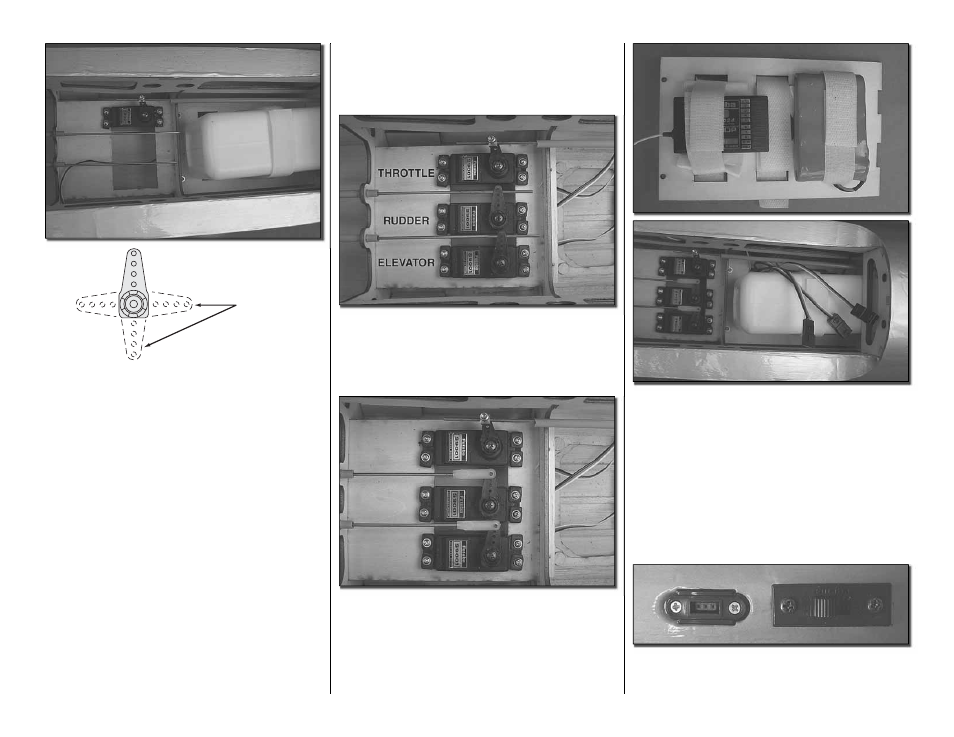
CUT OFF
UNUSED
ARMS
❏
11. Install the servo into the servo tray as shown.
Drill a 1/16" [1.6mm] hole through each of the servo
mounting holes. Insert and remove one of the servo
screws into each of the holes. Apply a couple drops of
thin CA into the holes to harden the threads. Once the
glue has hardened, attach the servo to the tray with
four #2 x 3/8" [10mm] screws and #2 fl at washers.
Remove the servo arm and cut off the unused arms.
Install a brass screw lock connector into the outer hole
of the remaining servo arm. Slide the wire through
the connector; re-attach the servo arm to the servo.
Secure the pushrod wire to the servo with a 4-40 x
1/8" [3mm] socket head cap screw.
INSTALL THE RADIO SYSTEM
❏
1. Remove the fuel tank and the tray from the
fuselage and set it aside.
❏
2. Use the wire pushrods as your guide for
positioning the rudder and elevator servos. Install the
servos using the same procedure used for the other
servos, mounting them onto the servo rails. Install the
servo arms onto the servos as shown.
❏
3. Using a 5/64 [2mm] drill bit, enlarge the outer
hole of the servo arms. Center the servos, elevator and
rudder. With a fi ne tip marker, mark the wires where
they align with the outer hole of the servo arms. Make
90° bends on the marks. Cut the wires so they are 3/8"
[10mm] in length after the bend. Insert the wires into
the servo arms and lock in place with nylon Faslinks.
❏
4. On the underside of the tray that the fuel tank
mounts to, install the receiver and battery onto ¼"
[6mm] foam and secure them to the tray with Velcro
straps. Plug the servos into the appropriate channels
in the receiver. Be sure to plug in a 12" [305mm]
servo extension for the retractable landing gear, fl aps
and aileron servos. Route the lead from the battery
through one of the slots for the Velcro so that after the
tray is re-installed you will be able to attach a switch
to the battery. Install the tray back into the fuselage
and re-install the fuel tank
❏
5. Plug your switch harness into the battery and
secure the connector with heat shrink tube, tape or
some other method to be sure the battery cannot