Top Flite TOPA0965 User Manual
Page 21
21
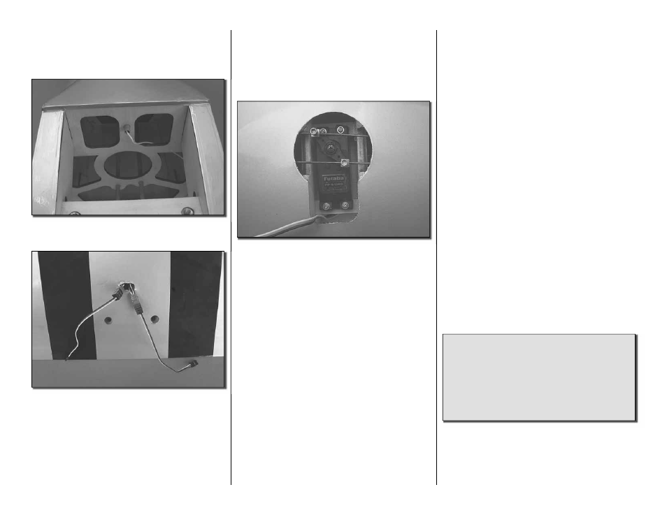
become unplugged. Mount the switch on the fuselage
opposite the exhaust. There are a number of after
market switch mounts. We used the Ernst Charge
Receptacle (ERNM3001) for Futaba radios.
❏
6. Route the antenna through the fuselage to the
antenna tube and feed the wire into the tube.
❏
7. Plug the two fl ap servos and the two aileron
servos into “Y” harnesses. Secure the servos to the
“Y” harness with shrink tubing, tape or some other
method to keep them from becoming unplugged.
❏
8. With your radio system turned on, adjust the
position of all of the servo arms and linkages until all
of the control surfaces are neutral.
FINAL SET-UP OF THE RETRACTABLE
LANDING GEAR SERVO
Mechanical retracts work very well when properly set
up but they can be a little tedious. The following will
help minimize your time required to set them properly.
❏
1. Depending on the brand of retract servo you use,
you may have to experiment with the length of the servo
arm. We used the standard six arm servo, cutting off
the arms except two that were 180 degree opposite
of each other. In the outer hole of each arm install a
brass screw lock connector and nylon retainer.
❏
2. Turn on your radio and plug the retract servo
into the receiver. Most likely your radio will have a two
position switch. In one direction the switch will raise the
landing gear; the other direction will lower it. Pick up
the servo arm. Slide one of the wires from the landing
gear into one of the brass screw lock connectors and
the other wire into the other connector. Install the
servo arm onto the servo but do not put the screw
in place to hold it to the servo and do not install the
screws into the screw lock connector.
❏
3. Flip the switch on the radio to see which way
the servo arm will rotate. The servo arm will need to
travel the same amount in both directions. Adjust the
position of the servo arm as needed to achieve this.
Install the screw to hold the servo arm in place on
the servo.
❏
4. The retracts move the landing gear up and down
by either pulling the wires or pushing them. Pulling
the wire will extend the landing gear. Find the switch
position that the servo arm will pull the wires. Pull
hard on the wire, locking the landing gear into the
extended position. Install a 4-40 x 1/8" [3mm] socket
head cap screw with threadlock into each of the
screw lock connectors, tightening the screw against
the wire.
❏
5. Flip the switch on the radio to make the landing
gear retract into the wheel. If everything is set
properly the wheels will retract into the wing and lock
into place. Flipping the switch back the other direction
will extend the gear and lock them into the extended
position. If your wheels do not extend or retract fully
you will need to adjust the amount of throw you are
getting from the servo. If you need more throw you
can consider using a longer servo arm. If you are
getting too much throw you can use a smaller servo
arm. If you are using a radio that has adjustable travel
volume you may be able to adjust the amount of throw
by adjusting it through the radio. Make whatever
adjustments are needed to get the landing gear to
lock in both the up and down positions. Be sure that
the servo does not bind or it will draw current from
the battery that could shorten your fl ight times. Have
a little patience and take the time to make sure the
gear work properly before your fi rst fl ight.
Did you know…The North American Texan trainer
is one of the most important aircraft of all time and
is universally recognized. First built as the NA-16
in 1935, the Texan was in continual production for
nearly 10 years and in active use for more than
fi ve decades. Primarily used as a trainer, the
Texan remains a favorite among Warbird collectors
around the world.