Build the wing – Top Flite TOPA0135 User Manual
Page 28
BUILD THE WING
NOTE: The wing panels are built “UPSIDE-
DOWN” on the plans. The jig tabs are attached
to what is, in the end, the TOP surface of the
wing. Since it is the standard convention to
show the Top View of the wing, and the wing
panels are built upside down, the LEFT wing
panel is built over the RIGHT Wing Top View
and vice-versa. This does not present any
problems; just be sure to build a left and a
right wing.
PREPARATION
❏
1. Locate the four 1/4" x 3/8" x 36" hard balsa
Wing Spars, then cut them 1/4" longer than shown
on the plans. Save the cut-off ends for the flap
servo hatch mounts.
❏
2. Sand a taper on one end of each of the four
1/8" x 3/8" x 18" balsa Spar Doublers as shown in
the sketch. Laminate a spar doubler to each spar
with the root end of the doubler aligned with the
root end of the spar.
❏
3. Before removing the 1/16" plywood Dihedral
Braces from the die-cut sheet, draw a centerline
on both pieces by connecting the punch marks.
❏
4. Remove all the die-cut 3/32" balsa Wing Ribs
and 1/16" ply (or 1/8" ply if installing fixed landing
gear) Rib Doublers. Smooth out any imperfections
with sandpaper. Be sure to keep the jig tabs
attached to the ribs.
❏
5. Ribs W-2 through W-6 have punch marks just
aft of the spar. Drill a 3/16" hole at each of these
marks for future installation of the aileron pushrods.
❏
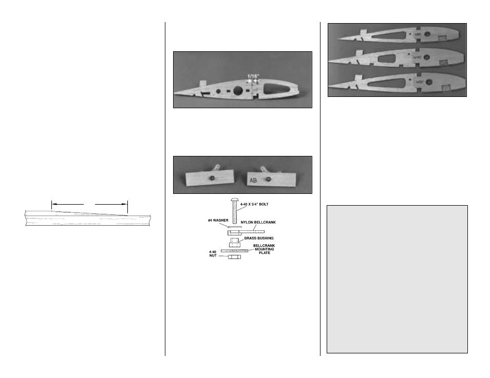
6. Use a straightedge to draw a line on either
side of both W-2 ribs 1/16" behind the spar notch.
Put marks on the line equal to the depth of the
deepest part of the forward notches.
❏
7. Drill 1/8" holes through the punch marks in the
two die-cut 1/8" plywood Aileron Bellcrank Plates
(AB). Assemble the bellcrank parts as shown in the
sketch (don’t worry, there is no
right and left – you
can’t build them backwards). Put a drop of
6-minute epoxy on the 4-40 nut and threads to
prevent the bellcrank from vibrating loose.
NOTE: If you haven’t already done so, now is
the time to decide if you are going to use
retractable or fixed landing gear.
Skip this step if installing retracts
❏
8. Locate wing ribs W-4, W-5, W-6 and plywood
doublers W4-F, W5-F and W6-F. Use thick CA to
glue the ribs and doublers together. Be sure to
make a LEFT and a RIGHT of each rib assembly.
Remove the shaded area with a hobby knife or
razor saw.
OUTER SPAR
SPAR DOUBLER
2"
- 28 -
RETRACT MODIFICATION FOR
CENTURY JET RETRACTS
The standard retract rail spacing in this kit is
designed to accept Robart #606 85 degree
retracts without modification. However, if you
elect to install the Century Jet Model’s retracts,
modify the rails and rib doublers to accept the
CJM retracts as follows. It will be easiest to do
this before framing the wing while the ribs and
doublers are easy to modify.
❏
1. Use the sketch on page 55 to modify the
1/16" plywood rib doublers before laminating
them to ribs W-5 and W-6.
❏
2. Make four new retract rails from 1/4" thick
5-ply aircraft plywood. The new dimensions
should be 1/4" x 17/32" x 3-1/16".