Install the engine – Top Flite TOPA0135 User Manual
Page 26
❏
11. Trim the ends of the aft bottom sheeting
even with F-9 and F-5D.
❏
12. Use a sanding block to sand the aft fuse
sheeting flush with the stringers so it tapers to the
bottom edge of the fin post.
❏
13. Bevel the front edge of the 1" x 2-1/2" x 7"
Aft Fuse Block to fit flush against 9-B. Sand the
aft edge flush with the fin post.
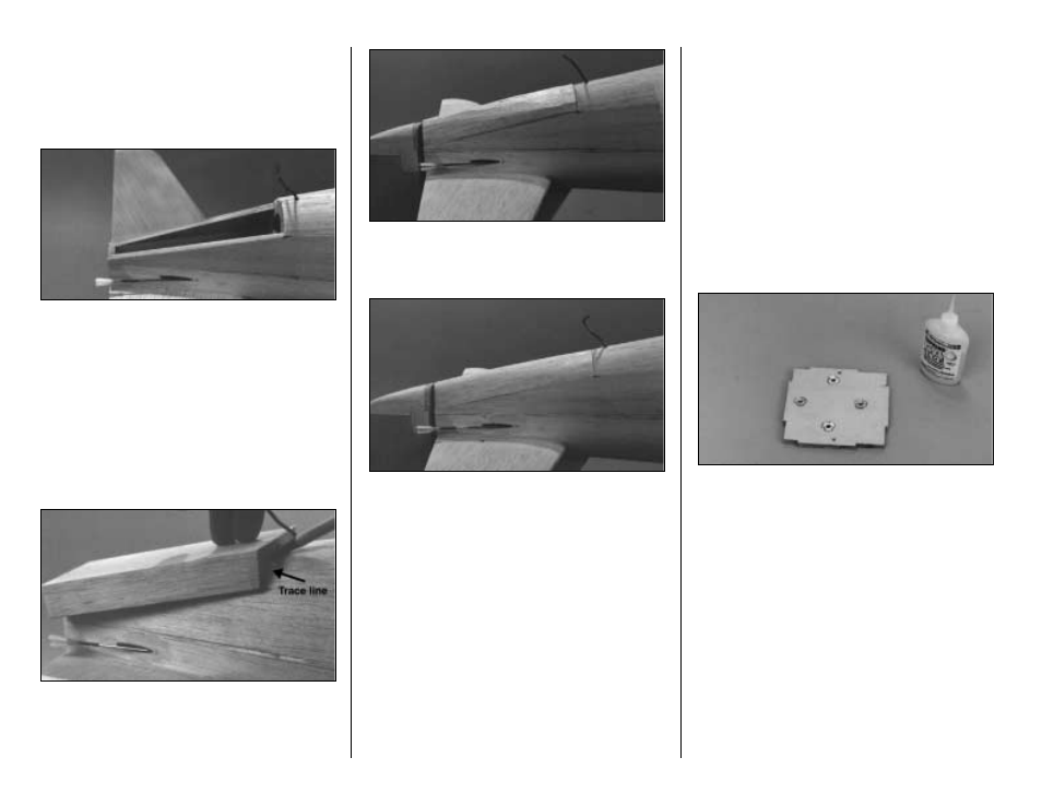
❏
14. Put the block on the fuselage and trace
around the underside and forward edge to form a
rough cutting outline. Tape the rudder in position
so that you can trace the outline on the aft edge of
the block.
❏
15. Remove the block, then use a hobby knife
and a razor plane to carve the shape to match the
outline you traced. Glue it in position when
satisfied with the shape.
❏
16. Continue shaping the aft fuse block to blend
with the fuse. Temporarily install the rudder, then
shape the aft fuse block and the rudder to blend
smoothly with the fuse.
❏
17. Use 30-minute epoxy to glue the 1/2" x 7/8"
x 1-1/4" Maple Wing Bolt Blocks in the fuselage
at the location shown on the plans.
Note: We will sheet between F-1 and F-2 when
we finish sheeting the belly pan.
INSTALL THE ENGINE
There are a variety of options when it comes to
engine selection. Our prototype P-47 weighed
approximately 10 lbs and flew extremely well with
the Super Tigre .75 2-stroke. When using a 1.20
4-stroke engine, due to the large amount of power
available the P-47 will have a tendency to climb as
full power is applied. This condition can be
controlled by adding an additional one degree of
down thrust to the engine.
NOTE: The following sequence shows the
installation of a Super Tigre .75 engine with the
cylinder mounted at a 45 degree angle towards
the bottom of the fuse. This orientation allows the
exhaust port of a 2-stroke engine to be connected
to a Top Flite In-Cowl Muffler and the engine
exhaust to exit near the bottom of the fuse.
❏
1. Drill four 7/32" holes through the laminated
Firewall for the engine mounting bolts at the
marked locations. Insert four 8-32 Blind Nuts into
the holes from the aft side and seat them with
gentle taps from a hammer. Wick thin CA around
the flange of each nut to secure it in position.
Avoid getting CA into the threads.
❏
2. Remove the spacer bar from the back of both
Engine Mount Halves and trim off any burrs.
Temporarily bolt the engine mount to the firewall
with four 8-32 x 1-1/4" Socket Head Cap Screws
with #8 Lock Washers and #8 Flat Washers.
Place the engine between the rails, adjusting the
width of the rails accordingly.
- 26 -