Top Flite TOPA0135 User Manual
Page 24
❏
24. Bevel the aft rudder pushrod tube so it
matches the angle of the fuselage. Install but don’t
glue the tube in the pushrod exit, then cut the
forward end so it extends 1/8" past the slot in the
plywood stab saddle.
❏
25. Slide the aft rudder pushrod through the aft
pushrod tube temporarily mounted in the fuselage.
Confirm that the alignment and location of the
pushrod and tube is correct. Make adjustments if
necessary, then permanantly glue the aft pushrod
tube to the fuselage.
❏
26. Prior to permanently connecting the aft
rudder pushrod, fill any gaps where the pushrod
tube exits the fuselage with some Micro Balloons
(Top Flite recommended) and epoxy. After it cures,
final sand to make a smooth, clean pushrod
tube exit.
❏
27. Permanantly install the aft rudder pushrod.
Hold the dual-end ball link with a pliers and screw
in the aft pushrod. Check the length of the rod, and
how far it is screwed into the dual-end ball link.
Make adjustments if required. Snap the ball link
onto the ball.
❏
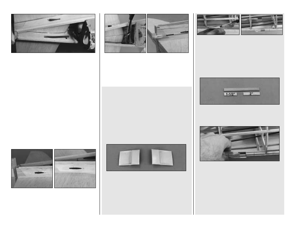
3. Hold an air exit up to the side stringer, then
use a ball-point pen to mark where the side
stringer interferes with it. Use a razor saw to
carefully cut through the side stringer and
sheeting. Remove this piece from the fuselage.
Perform this step on the other side of the fuselage.
❏
4. Glue a 1-1/2" long strip of 1/16" sheet to one
end of the 1/8" x 3/8" x 4-1/4" plywood strip and a
2" long piece to the other end. Make two of these
assemblies.
❏
5. Glue the main side stringer Braces to the
inside of the main side stringers. Refer to the top
and side view of the fuselage plans for location.
❏
6. Glue the remaining four 3/16" x 3/16" x 24"
aft fuselage stringers to the notches in
the formers.
FIT THE INTERCOOLER
AIR EXITS
NOTE: If you have decided to install the
supplied vacuum formed intercooler air exits,
follow the instructions below. If you elect not
to install the exits or wish to represent them
in a closed position, follow only step 6 and 7
below. Then, the closed air exits would
simply be represented by panel lines on your
finished model.
❏
1. Cut out the right and left vacuum formed
intercooler air exits along the cut lines.
❏
2. The main side stringers between F-6 and
F-7 need to be inset to clear the intercooler air
exits before adding the bottom sheeting. Mark
the location of the air exits on the fuselage side
stringers where shown on the plans.
- 24 -