Top Flite TOPA0135 User Manual
Page 23
❏
7. Cut two 3" long sticks from one of the
approximately 6" long scrap pieces of 3/16" x
3/16" stringers leftover from the top of the
fuselage. Bevel one end of each stick, then glue
one of them to the side of middle stringer on the
very bottom of the fuselage. The other one will be
glued on at step 11.
❏
8. Place the tailwheel assembly on the tailwheel
brace with the nylon bearing tube next to the
stringer. Mark the location with a pen then cut a
notch in the stringer for the nylon bearing.
❏
9. Test fit the tailwheel assembly with the
bearing in the notch. Rotate the tailwheel wire and
check for binding. Make adjustments if necessary.
❏
10. Put a few drops of 30-minute epoxy in the
holes of the plywood tailwheel brace and the bolt
holes of the nylon bracket. Screw the nylon
bracket to the brace with two #4 x 3/8" Sheet
Metal Screws.
❏
11. Force some epoxy into the notch of the
stringer and around the nylon bearing being
careful not to get any epoxy inside the tube. Glue
the remaining 3/16" x 3/16" x 3" stick to the other
side of the stringer to lock the nylon bearing
into position.
❏
12. Cut the .074" x 36" Threaded One End Rod
to approximate length by removing 7" from the
non-threaded end. Thread a Dual-Ended Ball
Link 14 full turns onto the threaded end.
❏
13. From the 6-1/2" long piece of inner pushrod
tube, cut 11 pieces approximately 3/8" in length
and slide four of them onto the rudder pushrod,
spaced as shown on the plans.
❏
14. Mark and cut the rudder and elevator
pushrod exits where shown on the fuselage plans.
Bevel the exits with a sharp knife or a round file to
allow the outer pushrod tubes to exit at the angle
shown on the plans.
❏
15. Place two 36" long grey Outer Pushrod
Tubes over the Elevator Pushrod Tube and
Forward Rudder Pushrod Tube drawings on the
top view of the fuselage plans. Cut them a few
inches longer than length shown. Use 220-grit
sandpaper to roughen the outside of the tubes so
glue will stick to them.
❏
16. From one of the short cut-off pieces of 36"
pushrod tube, cut a 5" long piece for the Aft
Rudder Pushrod Tube and sand the outside.
❏
17. Slide the forward rudder pushrod tube and
the elevator tube through the holes in the formers
and position them as shown on the plans with the
excess length forward of F-4 Note: Remember
you are looking at the top view of the plans.
Position the pushrods on opposite sides of the
fuse, when looking at the fuse from the bottom.
❏
18. If you haven’t already done so, cut the
rudder hinge slots. Temporarily install the rudder
onto the fin.
❏
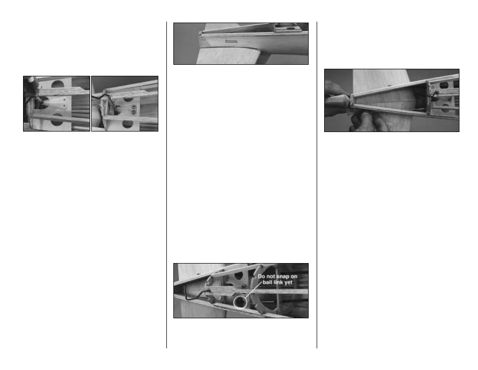
19. Install the Forward Rudder Pushrod
through the slot in the rear of the fuselage. Position
the dual-end ball link on the ball but do not snap
it on yet.
❏
20. Thread a Nylon Clevis onto the .074" x 12"
pushrod then place it over the Aft Rudder Pushrod
drawn on the plans and cut it 1/8" longer than shown.
❏
21. Temporarily snap a Small Control Horn
onto the clevis and slide a Threaded Coupler on
the end of the rod. Slide the control rod through the
pushrod exit in the aft end of the fuselage and
place the control horn on the rudder in the position
shown on the plans.
❏
22. Observe the location of the threaded
coupler and see if the length of the pushrod is
correct. With the rudder and tailwheel in neutral
position the threaded rod should be able to
screw into the dual-end ball link about 3/16".
Make adjustments to the length of the pushrod if
required.
❏
23. Once the threaded coupler is soldered to
the pushrod and the system is hooked up and
closed in, some adjustment may be made by
screwing or unscrewing the clevis but the more
accurate it is now, the less adjustment you may
have to make later. Slide one of the 3/8" spacers
onto the aft rudder pushrod, then use silver solder
to solder the threaded coupler onto the pushrod.
- 23 -