System connection examples – Toa TS-900 Series User Manual
Page 24
24
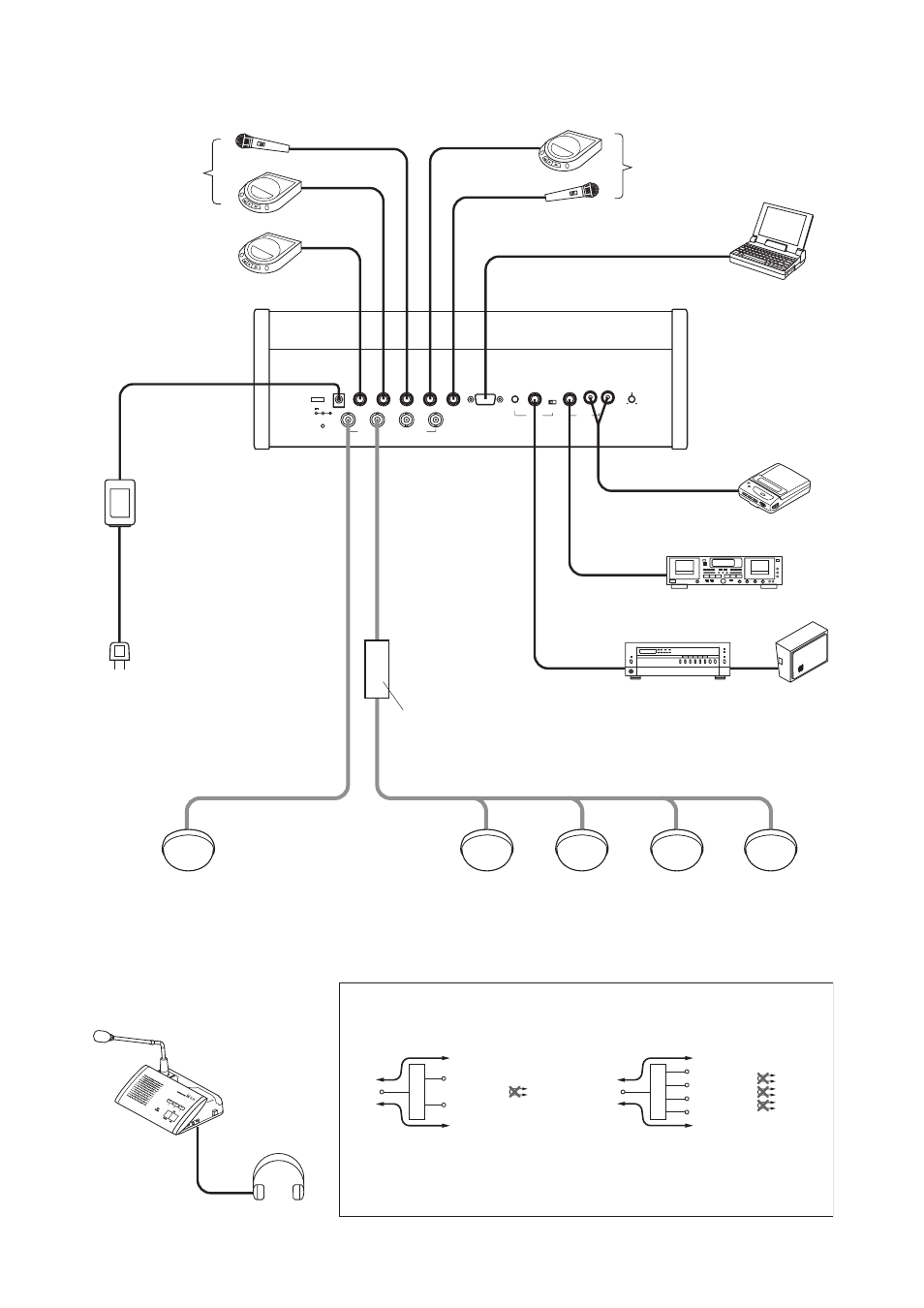
9. SYSTEM CONNECTION EXAMPLES
INFRARED TRANSMITTER/RECEIVER
SHORT
AUX3
DC24V 3A(MAX)
AUX2
MIC2
MIC1
EXT CONTROL
LEVEL
CHIME
LINE OUT
REC OUT
MIX CUT
AUX3
AUX1
Distributor block diagram
To avoid an increase in loss, do not perform connections
between distribution terminals.
Note:
[YW-1022]
[YW-1024]
Central unit TS-900
PC
Headphone
Cassette player
Alternate recording deck
Speaker
Amplifier
For the base language channel
For the translation
language channel
For the base language
and translation language
channels
AC adapter
(supplied with the TS-900)
Power cord
(supplied with the TS-900)
Chairman unit TS-901
or
Delegate unit TS-902
Infrared transmitter/receiver
TS-905 or TS-907
Distributor
YW-1024 (4-branch distributor)
or
YW-1022 (2-branch distributor)
For details of the installation and connection of the Infrared Transmitter/Receiver unit,
please refer to
p. 27
"11. INSTALLATION AND CONNECTIONS."
Distributor
Distribution 1
Loss of 4.5dB
Loss of 4.5dB
Distribution 2
Mixing
Impossible
Distributor
Distribution 1
Loss of 8.5dB
Loss of 8.5dB
Distribution 2
Mixing
Distribution 3
Distribution 4
Impossible
Impossible
Impossible