Bottom – Toa TS-900 Series User Manual
Page 11
11
INFRARED TRANSMITTER/RECEIVER
SHORT
AUX3
DC24V 3A(MAX)
AUX2
MIC2
MIC1
EXT CONTROL
LEVEL
CHIME
LINE OUT
REC OUT
MIX CUT
AUX3
AUX1
23 24
25
26
27
28
29
30 31 32
34
33
35
36
37
38
[Bottom]
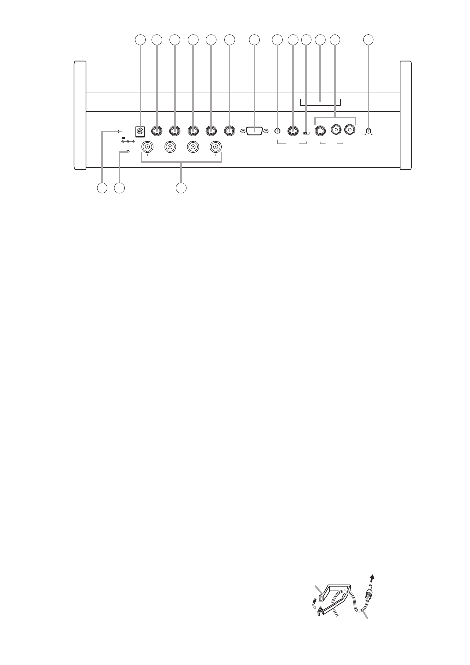
23. DC input
Connect the supplied AC adapter to this terminal.
24. AUX 3 input terminal
Connect a CD player, tape recorder, or other
similar equipment to this terminal. Speech input
connected to this terminal is relayed to both the
base and translation language channels.
25. AUX 2 input terminal
Connect a CD player, tape recorder, or other
similar equipment to this terminal. Speech input
connected to this terminal is relayed to the
translation language channel.
26. MIC 2 input terminal
Connect a wired microphone to this terminal.
Speech input from the microphone connected to
this terminal is relayed to the translation
language channel.
27. AUX 1 input terminal
Connect a CD player, tape recorder, or other
similar equipment to this terminal. Speech input
connected to this terminal is relayed to the base
language channel.
28. MIC 1 input terminal
Connect a wired microphone to this terminal.
Speech input from the microphone connected to
this terminal is relayed to the base language
channel.
29. External control terminal
Connect this terminal to the serial port of a PC,
operation panel, or other external control
equipment.
30. Level volume control
Adjusts the line output volume.
31. Line output terminal
Connect an amplifier, etc. for public address
applications. Speech input from the Chairman
unit, Delegate unit, or MIC 1, AUX 1, or AUX 3
terminals is output to this terminal. The settings
of Microphone Mix/Cut switch (10) and AUX 3
Output Mix/Cut switch (32) determine whether or
not such speech input is output.
32. AUX 3 output Mix/Cut switch
Determines whether or not speech input is
relayed from AUX 3 terminal to the line output.
Set this switch to MIX in normal use, and to CUT
to enable conference participants in other rooms
to avoid potential audio feedback while speaking.
33. Marking plate
Shows the Manufacturer's Name, Model Name,
and Electrical Rating.
34. Recording output terminal
Connect an Alternate Recording Deck or MD
recorder. An amplifier can also be connected for
public address applications. The same speech
signal as the line output and that of AUX 3
terminal are output to this terminal.
35. Priority chime volume control
Adjusts the output volume of the chime tone that
sounds when the Priority Speech key on the
Chairman unit is pressed.
36. Infrared transmitter/receiver unit I/O terminals
Connect the Infrared Transmitter/Receiver unit or
distributor to this terminal. By using the YW-1022
(2-branch distributor) and/or YW-1024 (4-branch
distributor), the following maximum number of
Infrared Transmitter/Receiver units can be
connected: 16 units when they are all TS-905
units, 12 units when they are all TS-907 units.
(Also 12 units when both models are mixed.)
37. Short circuit indicator
Lights when the Infrared Transmitter/Receiver
unit or its connected cable is shorted.
38. Cable clip
Run the AC adapter cable through this clip to
prevent its plug from being removed from the DC
input.
Cable clip
AC adapter cable
To the DC input