Nomenclature and functions, Central unit ts-800 [top – Toa TS-800 Series User Manual
Page 9
MIC
TIME OUT
OFF
PRIORITY
TEST
Ch4
Ch3
Ch2
Ch1
BATTERY
DATA
A: FIRST
B: LATEST
C: FIRST: FIXED, NEXT: LATEST
A B C
MIC
DATA–EXT–PRIORITY
UNIT
MAX
1 2 4
ON
AUX
10
0
10
0
10
0
10
0
CENTRAL UNIT TS-800
HEADPHONES
POWER
FUNCTION SETTING
MIC UNIT
MIC UNIT INPUT
INPUT
1
2
3
4
5
6
7
8
9
10
11
12
13
14
15
9
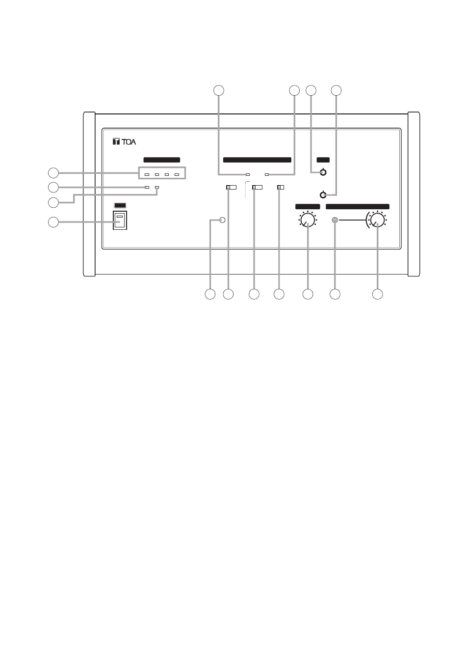
5. NOMENCLATURE AND FUNCTIONS
5.1. Central Unit TS-800
[Top]
1. Power switch
Setting this switch to the ON position causes the
Power indicator to light.
2. Audio signal receiving indicators
[Ch1/Ch2/Ch3/Ch4]
Light up when audio signals are received from
either Chairman or Delegate units. Audio signals
are transmitted or received through 4 channels.
The number of channels to be used can be set
with the Simultaneous Speaker No. Setting switch
(10). These indicators light in the same number as
that of the Chairman or Delegate units currently
being used for speech. (Which indicator will light is
not specified.)
3. Data signal receiving indicator
Lights when control data is received from the
Chairman or Delegate unit.
4. Battery indicator
Flashes when the lithium-ion battery of the
Chairman or Delegate unit nears complete
discharge. (In this event, the Microphone In-Use
indicator and the Speech indicator on the
corresponding unit also flash.)
Note
Be sure to replace the lithium-ion battery of the
corresponding unit immediately if this indicator
begins to flash.
5. External control communication indicator
Remains lit during communications with a
computer (PC) or operation panel connected to
the RS-232C terminal.
6. External control priority indicator
Either lights or flashes when a PC or operation
panel connected to the RS-232C terminal
performs priority operation. In this event, three
function setting switches (10), (11), and (12)
cannot be used.
7. AUX input volume control
Adjusts the input signal level of the AUX Input
Terminal (17) located on the rear panel.
8. MIC input volume control
Adjusts the input level of the MIC Input Terminal
(18) on the rear panel.
9. Installation check button
Installation status for the Infrared Transmitter/Receiver,
Chairman unit, and Delegate unit can be checked.
(Refer to p. 44.)