System connection examples – Toa TS-800 Series User Manual
Page 22
22
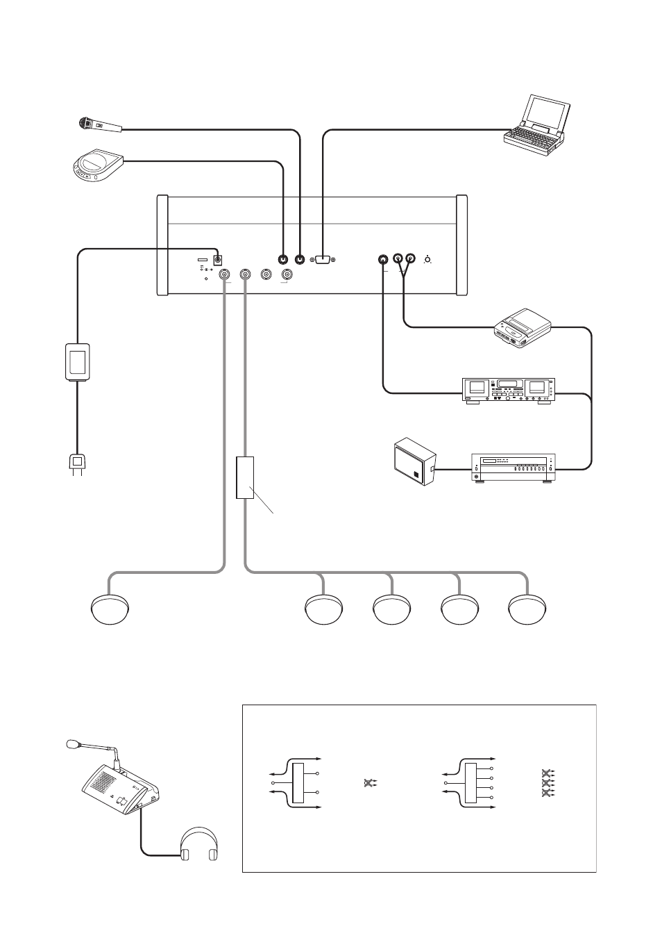
8. SYSTEM CONNECTION EXAMPLES
INFRARED TRANSMITTER/RECEIVER
SHORT
DC24V 3A(MAX)
MIC
RS-232C
CHIME
REC OUT
AUX
CHAIRMAN
UNIT TS
-801
Distributor block diagram
To avoid an increase in loss, do not perform connections
between distribution terminals.
Note:
[YW-1022]
[YW-1024]
Central unit TS-800
PC
Headphone
Cassette player
Alternate recording deck
Speaker
Amplifier
AC adapter
(supplied with the TS-800)
Power cord
(supplied with the TS-800)
Chairman unit TS-801
or
Delegate unit TS-802
Infrared transmitter/receiver
TS-905 or TS-907
Distributor
YW-1024 (4-branch distributor)
or
YW-1022 (2-branch distributor)
For details of the installation and connection of the Infrared Transmitter/Receiver unit,
please refer to
p. 25
"10. INSTALLATION AND CONNECTIONS."
Distributor
Distribution 1
Loss of 4.5dB
Loss of 4.5dB
Distribution 2
Mixing
Impossible
Distributor
Distribution 1
Loss of 8.5dB
Loss of 8.5dB
Distribution 2
Mixing
Distribution 3
Distribution 4
Impossible
Impossible
Impossible
- D-2000 Series Installation (84 pages)
- DD-2000 Series Manual (24 pages)
- D-2000 Series Read Me First (12 pages)
- D-2012AS (2 pages)
- D-2012C (4 pages)
- D-901 (96 pages)
- CR-273 (20 pages)
- CR-413-6 (20 pages)
- EV-20R (20 pages)
- MP-1216 (8 pages)
- MB-WT3 (2 pages)
- MT-251H (1 page)
- F-2322C (12 pages)
- F-2852C (12 pages)
- SC-630 (2 pages)
- ES-0851 (4 pages)
- ES-C0651 (4 pages)
- F-1000B (18 pages)
- F-122C (12 pages)
- F-122CU (20 pages)
- F-122CU2 (16 pages)
- F-1300B (18 pages)
- F-1522SC (8 pages)
- AN-9001 (1 page)
- C-AL80 (16 pages)
- DP-K1 (28 pages)
- DP-K1 (102 pages)
- DP-L2 v.2.00 (28 pages)
- DP-SP3 Protocol (14 pages)
- DP-SP3 (24 pages)
- DP-SP3 (75 pages)
- E-232 (8 pages)
- AT-063AP (4 pages)
- BS-1015BSB (8 pages)
- BS-1030B (4 pages)
- BS-634 (4 pages)
- BS-1034EN (8 pages)
- BS-1110W (4 pages)
- BS-301B (8 pages)
- BS-301B AS (4 pages)
- MB-WT1 (1 page)
- S-D7300 (16 pages)
- VX-200SP-2 (24 pages)
- YA-1000A (1 page)
- ZM-9001 (2 pages)