TeeJet 844 Sprayer Control User Manual
Page 8
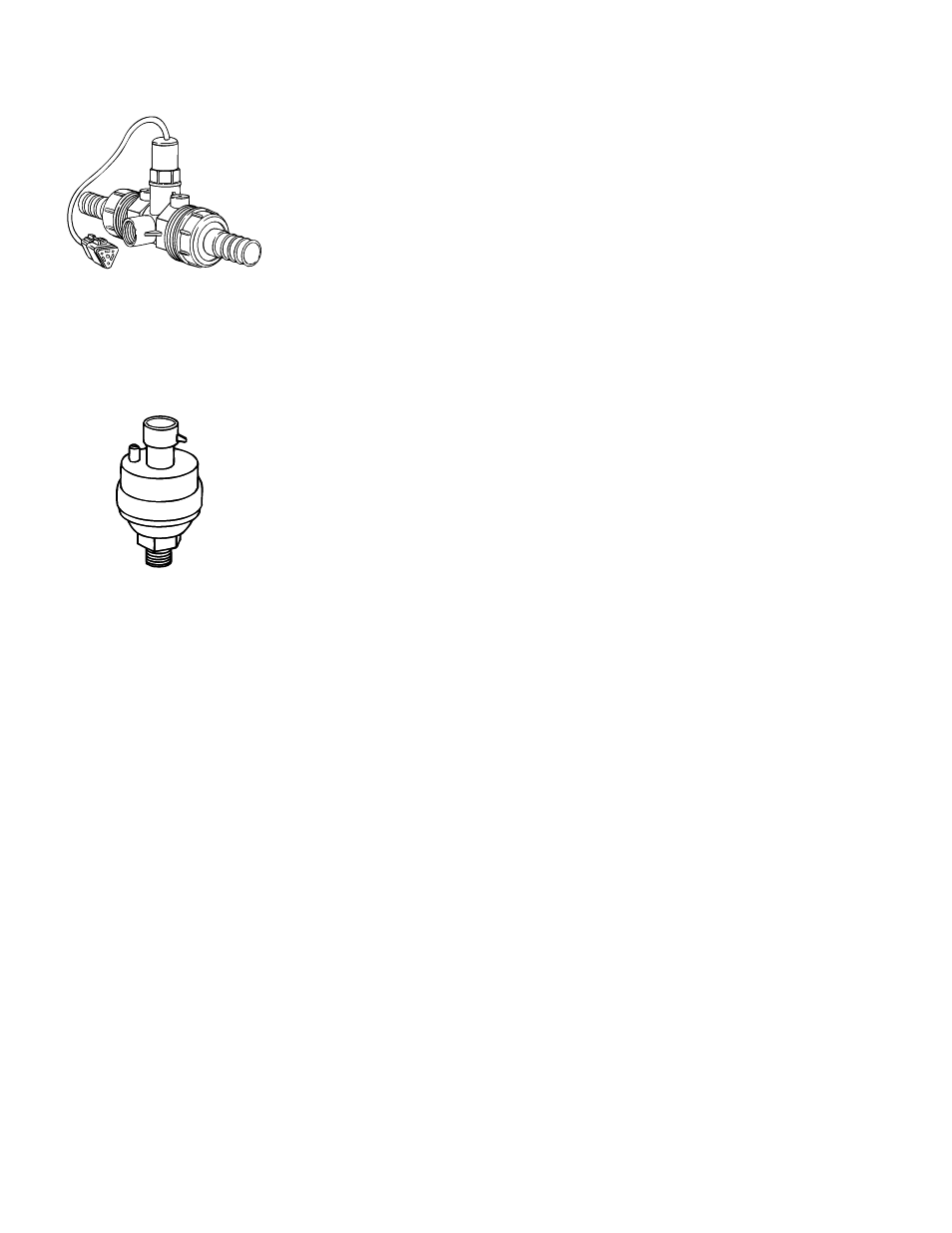
FLOW METER
To ensure accurate readings, the flow meter (if used) must be mounted 10˝ to 12˝
(25-35 cm) from other pipe fittings, preferably in a vertical position with the flow
going up. It should also be mounted with direction of flow arrow pointing toward
the boom control valves. Refer to Figures 7A and 8.
Be sure the flow meter is plumbed so that all liquid passing through it is routed to
the booms and not back to the tank. When using three-way boom control valves,
refer to page 22 of this manual for programming guidelines.
BOOM CONTROL VALVES
The Boom Control Valves are connected in tandem and centered in front of the
boom sections. See the Control Valve Instruction Manual for mounting
instructions. If using three-way valves, refer to the instruction manual of the
valves you are using for valve calibration instructions.
PRESSURE TRANSDUCER
The pressure transducer (if used) should be installed as close to the spray tips
as possible. Normally this is at the boom control valve assembly. Refer to pages
4 and 5, Figures 7 and 8A. Mount the unit vertically on a short stand pipe to
help protect the sensor.
NOTE: Pressure drop, to some degree, is found in most plumbing systems.
Pressure drop is created when there is any kind of restriction in the spray
line reducing flow rate and is quite often produced between the boom
control valve assembly and the spray tips. If one of the boom sections on
the sprayer is always used, the pressure transducer can be installed on
that particular boom section, therefore minimizing any potential pressure
drops between the sensor and spray tips. If the pressure drop in your
system is greater than 5 psi (0.3 bar), you should consider this as an
alternative location for the pressure transducer.
Check all components to make sure they are mounted securely to avoid
excessive vibration.
6