Mounting sprayer components, Pressure regulator in bypass mode – TeeJet 844 Sprayer Control User Manual
Page 6
4
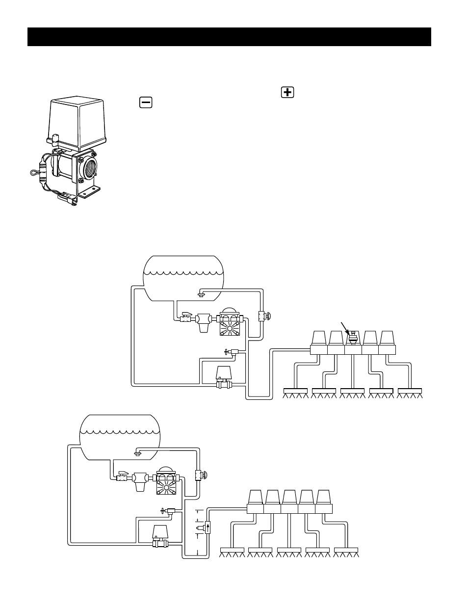
PRESSURE REGULATOR IN BYPASS MODE
All pressure regulating valves for the 844 will be wired for use in a by-pass
system. While plumbed in a by-pass mode, with the Auto/Man key in the “MAN”
mode, the valve should close when the key is depressed and open when the
key is depressed.
The pressure regulating valve can also be mounted in a throttling situation as an
alternative location. Refer to page 5, and Figures 8 and 8A.
NOTE: The diagrams in Figures 7, 7A, 8 and 8A are shown as general
guidelines to follow when plumbing 844 components. The type of pump
used and location of other components can vary from sprayer to sprayer.
It is important to ensure that if a pressure transducer is used that it is
located as close to the spray tips as possible. Normally this is at the boom
control valves. However, if one particular boom section is always used, the
pressure transducer can be mounted on that particular boom section. If a
flow meter is used, ensure that all of the flow going through the flow meter
is directed to the spray tips. Make sure that proper distance is allowed on
the inlet and outlet side of the flow meter (refer to figures 7A and 8).
Mounting Sprayer Components
F
IGURE
7
B
YPASS
P
LUMBING
D
IAGRAM
P
RESSURE
B
ASED
S
YSTEM
TANK
JET AGITATOR
DIAPHRAGM
PUMP
TANK SHUT-OFF
STRAINER
PRESSURE
REGULATING
VALVE
AGITATOR
VALVE
PRESSURE RELIEF VALVE
PRESSURE
TRANSDUCER
ELECTRIC
BALL VALVES
BOOM SECTIONS
TANK
JET AGITATOR
DIAPHRAGM
PUMP
TANK SHUT-OFF
STRAINER
PRESSURE
REGULATING
VALVE
AGITATOR
VALVE
PRESSURE RELIEF VALVE
FLOW METER
5-7”
(12-17 CM)
10-12”
(25-35 CM)
ELECTRIC
BALL VALVES
BOOM SECTIONS
F
IGURE
7A
B
YPASS
P
LUMBING
D
IAGRAM
F
LOW
B
ASED
S
YSTEM