Making the connections, S t e p – TeeJet 844 Sprayer Control User Manual
Page 17
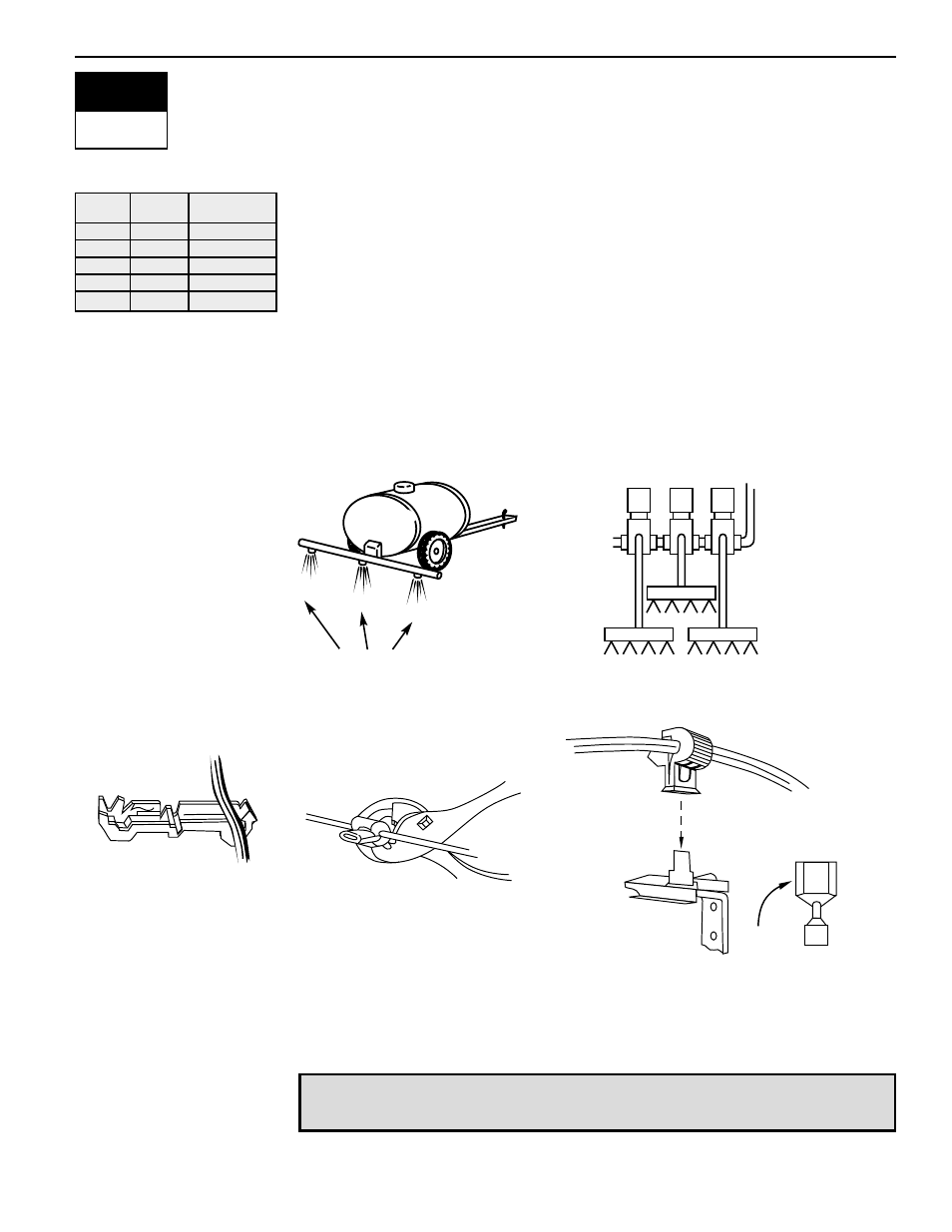
Making the Connections
Now, extend the cable containing the leads to the Flow meter or Pressure
Sensor, and Wheel Sensor or Radar Sensor to the furthest component. Select
the appropriate lead and connect to this component. Run the cable to the other
component, taking care to safely secure the cable along the route. Refer to
figure 11 on page 14.
Repeat this procedure with the cable containing the leads to the Pressure
Regulating Valve and the Boom Control Valves. Refer to the chart at left when
attaching the boom section wires. This cable also includes one or two black wires
for ground connections. T-tap connectors must be attached to these wires to
connect them to the boom control valves, which should be evenly distributed
across the two.
If both the flow meter and pressure transducer are not used simultaneously, there
will be one extra connection on the sensor end cable. Simply tie this part of the
cable back as it will not be used.
When all connections have been made, connect the large plugs into the
appropriate cable leads on the side of the Control Console.
Note: The 844 is designed to handle a maximum of 4 amps per boom section.
Valves requiring DPDT switches are not compatible with the 844.
15
2
CONNECT
S T E P
You are now ready to begin the programming
of the TeeJet Model 844 Sprayer Control.
1
White
2
1
Green
3
2
Yellow
4
3
Orange
5
Blue
5 Section 3 Section
Color
B
OOM
C
ONTROL
V
ALVE
W
IRE
C
OLORS
VS
. B
OOM
S
ECTION
#
S
TEP
A
S
TEP
B
S
TEP
C
SOLENOID
VALVES
BOOM SECTIONS
BOOM SECTIONS
1
2 3
BALL VALVE
CONNECTOR
TO TERMINAL
OF VALVE
1
2
3