Section 4.8.1 for det – SilentKnight 5499 9A Distributed Power Module User Manual
Page 22
5499 Distributed Power Module Installation Manual
18
151253
4.8.1
Selecting the Standard Input/Output Configurations
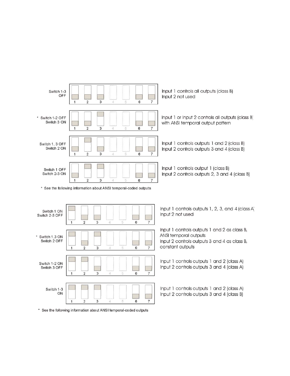
Figure 4-7 and Figure 4-8 show the position of each switch for the non-synchronized
input and output configurations. The position of Switches 4 and 5 does not affect the
relationship of inputs to outputs.
Note: The 5499 checks switches 1, 2, 3, and 6 only when powering up the 5499. If you change these
switch settings, you must remove both the AC power and the battery to make the 5499 recognize
the new settings.
Figure 4-7 Setting DIP Switches 1-3
Figure 4-8 Setting DIP Switches 1-3 (Continued)
Note: For 100 mS input signal debounce with no synchronization DIP switches 6 and 7 must be turned
On.
See also other documents in the category SilentKnight Safety:
- 5104 Digital Alarm Communicator Transmitter 6 Zone (48 pages)
- 5128 Digital Alarm Communicator Transmitter (42 pages)
- 5217 10-Zone Expander for 5208 (2 pages)
- 5220 Direct Connect Module (2 pages)
- 5235 Remote Annunciator for 5208 (2 pages)
- 5280 Status Display Module for 5208 (2 pages)
- 5495 6A Distributed Power Module (52 pages)
- 5496 6A Intelligent Remote Power Supply (38 pages)
- 5600 (114 pages)
- 5660 Silent Knight Software Suite (28 pages)
- 5670 IntelliKnight Facility Management Software (24 pages)
- 5700 (180 pages)
- 5808 (180 pages)
- 5815RMK Remote Mounting Kit (2 pages)
- 5815XL Signal Circuit Expander (2 pages)
- 5820XL-EVS (236 pages)
- 5824 Serial/Parallel Module (2 pages)
- 5860/5860R Remote Annunciator (2 pages)
- 5865-3/5865-4 Remote LED Annunciator (2 pages)
- 5880 LED Driver Module (2 pages)
- 5883 Relay Interface Board (4 pages)
- 5895XL 6A Intelligent Remote Power Supply (56 pages)
- B200S Intelligent Sounder Base with CO Support (4 pages)
- B200S-LF - Low Frequency Intelligent Sounder Base (4 pages)
- B200SR Sounder Base (4 pages)
- B200SR-LF Low Frequency Intelligent Sounder Base (4 pages)
- B210LP 6 Mounting Base (2 pages)
- B224BI 6 Mounting Base w/Built-in Isolator (2 pages)
- B224RB 6 Mounting Base w/Built-in Relay (4 pages)
- B501 4 Mounting Base (2 pages)
- Central Station Monitoring List (1 page)
- Document Revision History (4 pages)
- EVS (74 pages)
- EVS-CE4 (2 pages)
- EVS-RVM (2 pages)
- EVS-VCM (2 pages)
- FFT (1 page)
- FFT-24 (2 pages)
- FFT-24 Installation (1 page)
- FFT-FPJ (1 page)
- FFT-HSC (1 page)
- FFT-STSS and FFT-STSR (2 pages)
- HFS-D (4 pages)
- HFS-MM (1 page)