Cisco 6500 User Manual
Page 55
4-55
Cisco IOS Software Configuration Guide, Release 12.2SX
OL-13013-06
Chapter 4 Configuring Virtual Switching Systems
Upgrading a VSS
This example shows how to perform an FSU:
Router# config terminal
Router(config)# no boot system
Router(config)# config-register 0x2102
Router(config)# boot system flash disk0:image_name
Router(config)# end
Router# copy running-config startup-config
Router# redundancy reload peer
Router# redundancy force-switchover
Performing an Enhanced Fast Software Upgrade of a VSS
An eFSU uses the same commands and software infrastructure as an in-service software upgrade (ISSU).
The eFSU differs from an ISSU in that it resets the modules, which results in a brief traffic interruption.
The eFSU sequence for a VSS follows the same logical steps as the single-chassis eFSU described in the
“Performing an Enhanced Fast Software Upgrade” section on page 5-5
, but the procedure applies to the
VSS active and VSS standby supervisor engine in each chassis, instead of two supervisor engines in one
chassis. During an eFSU, the VSS standby chassis, including the supervisor engine and modules, is
upgraded and brought up in a stateful switchover (SSO) mode. The eFSU process then forces a
switchover and performs the same upgrade on the other chassis, which becomes the new VSS standby.
Note
VSS mode supports only one supervisor engine in each chassis. If another supervisor resides in the
chassis it will act as the DFC.
This section contains the following topics:
•
eFSU Restrictions and Guidelines, page 4-56
•
eFSU Stages for a VSS Upgrade, page 4-57
•
Configuring and Performing an eFSU Upgrade, page 4-58
•
eFSU Upgrade Example, page 4-66
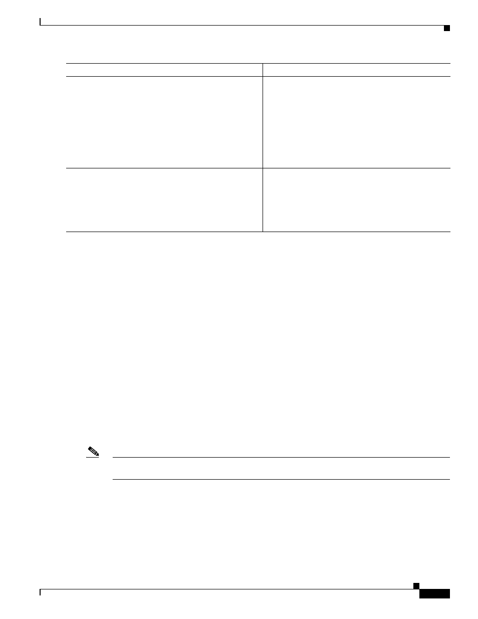
Step 8
Router# redundancy reload peer
Reloads the VSS standby chassis and brings it back
online running the new version of the Cisco IOS
software. Due to the software version mismatch between
the two chassis, the VSS standby chassis will be in RPR
redundancy mode.
Note
Before reloading the VSS standby chassis, make
sure you wait long enough to ensure that all
configuration synchronization changes have
completed.
Step 9
Router# redundancy force-switchover
Forces the VSS standby chassis to assume the role of the
VSS active chassis running the new Cisco IOS image.
The modules are reloaded and the module software is
downloaded from the new VSS active chassis.
The old VSS active chassis reboots with the new image
and becomes the VSS standby chassis.
Command
Purpose