Mec failure scenarios, Figure 4-8 – Cisco 6500 User Manual
Page 15
4-15
Cisco IOS Software Configuration Guide, Release 12.2SX
OL-13013-06
Chapter 4 Configuring Virtual Switching Systems
Understanding Virtual Switching Systems
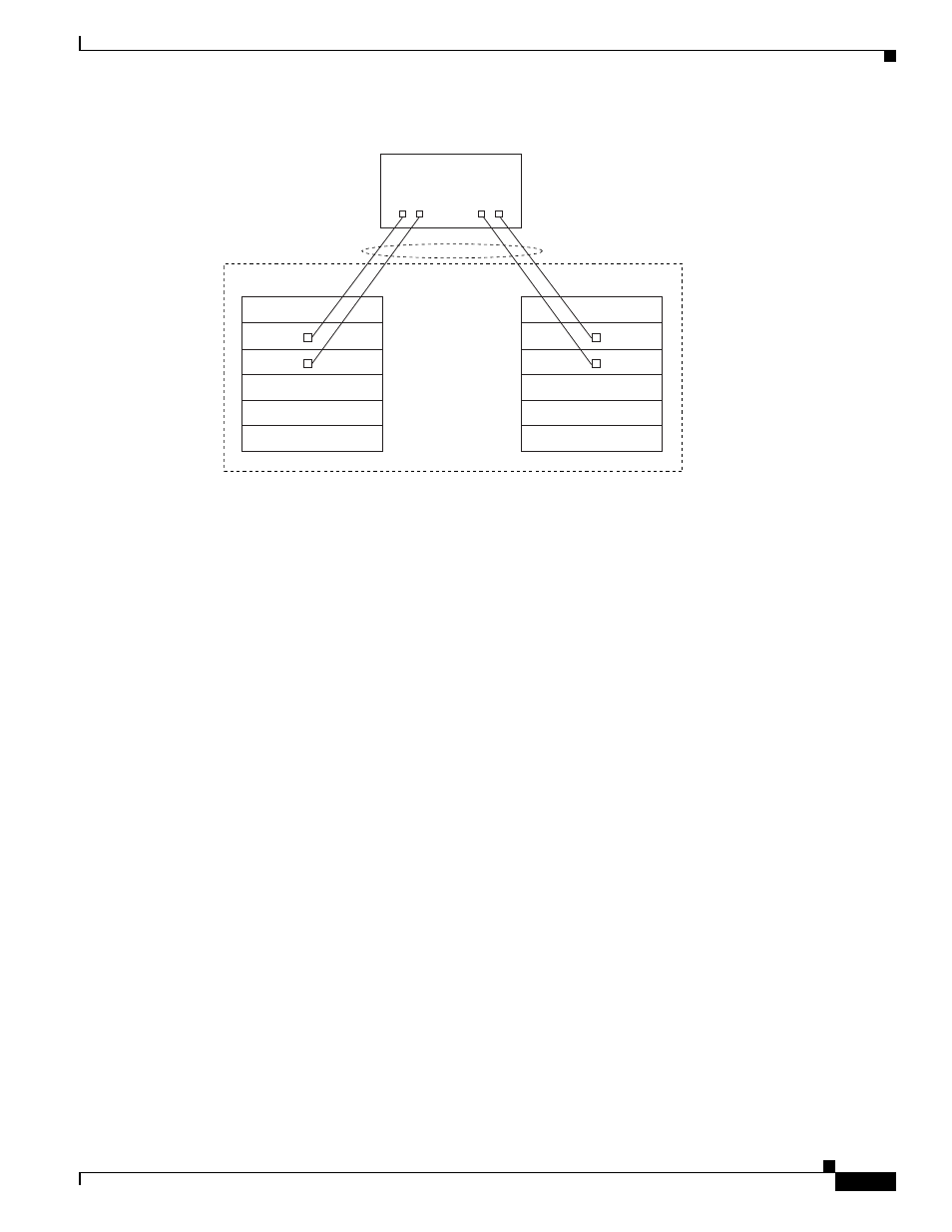
Figure 4-8
MEC Topology
MEC Failure Scenarios
We recommend that you configure the MEC with at least one link to each chassis. This configuration
conserves VSL bandwidth (traffic egress link is on the same chassis as the ingress link), and increases
network reliability (if one VSS supervisor engine fails, the MEC is still operational).
The following sections describe possible failures and the resulting impacts:
•
Single MEC Link Failure, page 4-15
•
All MEC Links to the VSS Active Chassis Fail, page 4-15
•
All MEC Links to the VSS Standby Chassis Fail, page 4-16
•
•
VSS Standby Chassis Failure, page 4-16
•
VSS Active Chassis Failure, page 4-16
•
Failed Chassis MEC Recovery, page 4-16
Single MEC Link Failure
If a link within the MEC fails (and other links in the MEC are still operational), the MEC redistributes
the load among the operational links, as in a regular port.
All MEC Links to the VSS Active Chassis Fail
If all links to the VSS active chassis fail, the MEC becomes a regular EtherChannel with operational
links to the VSS standby chassis.
Data traffic terminating on the VSS active chassis reaches the MEC by crossing the VSL to the VSS
standby chassis. Control protocols continue to run in the VSS active chassis. Protocol messages reach
the MEC by crossing the VSL.
Virtual switch
Supervisor
engine
Supervisor
engine
Active chassis
Standby chassis
181327
Router, switch
or server
MEC