Converting to a vss – Cisco 6500 User Manual
Page 30
4-30
Cisco IOS Software Configuration Guide, Release 12.2SX
OL-13013-06
Chapter 4 Configuring Virtual Switching Systems
Configuring a VSS
Converting to a VSS
By default, the Catalyst 6500 series switch is configured to operate in standalone mode (the switch is a
single chassis). The VSS combines two standalone switches into one virtual switch, operating in virtual
switch mode.
Note
When you convert two standalone switches into one VSS, all non-VSL configuration settings on the VSS
standby chassis will revert to the default configuration.
To convert two standalone chassis into a VSS, you perform the following major activities:
•
Save the standalone configuration files.
•
Configure SSO and NSF on each chassis.
•
Configure each chassis as a VSS.
•
Convert to a VSS.
•
Configure the peer VSL information.
In virtual switch mode, both chassis use the same configuration file. When you make configuration
changes on the VSS active chassis, these changes are automatically propagated to the VSS standby
chassis.
The tasks required to convert the standalone chassis to a VSS are detailed in the following sections:
•
Backing Up the Standalone Configuration, page 4-31
•
Configuring SSO and NSF, page 4-31
•
Assigning Virtual Switch Domain and Switch Numbers, page 4-32
•
Configuring VSL Port Channel and Ports, page 4-33
•
Converting the Chassis to Virtual Switch Mode, page 4-34
•
(Optional) Configuring VSS Standby Chassis Modules, page 4-35
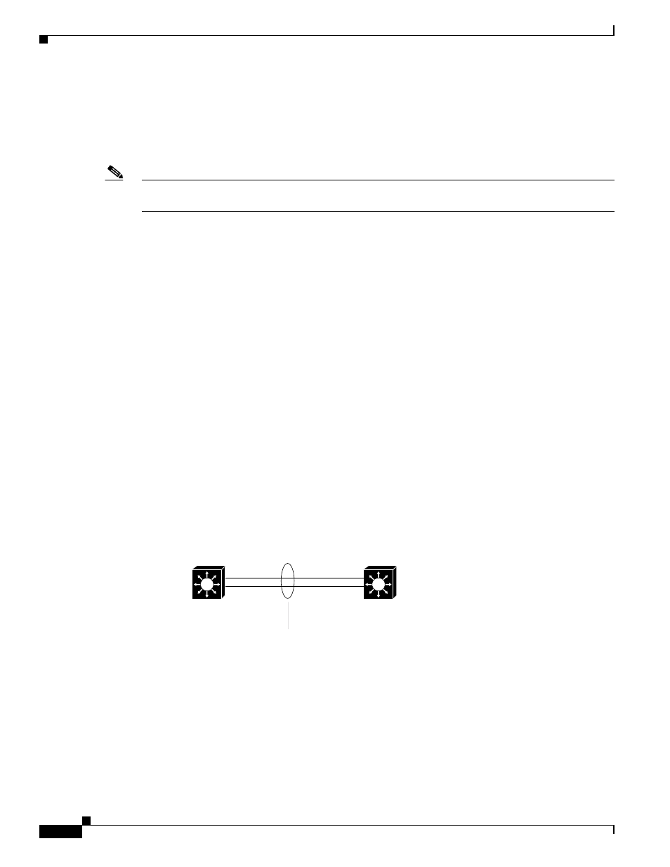
In the procedures that follow, the example commands assume the configuration shown in
.
Figure 4-9
Example VSS
Two chassis, A and B, are converted into a VSS with virtual switch domain 100. Interface 10-Gigabit
Ethernet 5/1 on Switch 1 is connected to interface 10-Gigabit Ethernet 5/2 on Switch 2 to form the VSL.
181325
Virtual switch link
(VSL)
Chassis A
(Switch 1)
Chassis B
(Switch 2)
T 5/1
T 5/2