0 maintenance (cont'd), Warning – Reznor CAUA Users Manual User Manual
Page 4
Form O-CAUA, Page 4
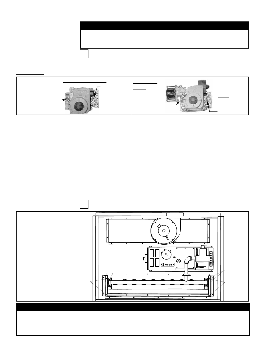
2.2.3 Gas Valve
Single-Stage Valve
Two-Stage
Valve
1/8" INLET
Pressure Tap
1/8”
Outlet
Pressure
Tap
1/8" INLET
Pressure Tap
1/8”
Outlet
Pressure
Tap
FIGURE 2
2) With the manual valve turned off to prevent flow to the gas valve, connect a
manometer to the 1/8” inlet pressure tap in the valve.
NOTE: A manometer (fluid-
filled gauge) with an inches water column scale is recommended.
3) With the field-installed manual valve remaining closed, observe the manometer
for two to three minutes for an indication of gas pressure. No pressure should be
indicated on the manometer.
If the manometer indicates a gas pressure, the field-installed manual gas valve
must be replaced or repaired before the combination gas valve can be checked.
4) If the manometer does not indicate gas pressure, slowly open the field-installed
manual gas valve. After the manometer's indicated gas pressure has reached
equilibrium, close the manual shutoff valve. Observe the gas pressure. There
should be no loss of gas pressure on the manometer. If the manometer indicates
a loss of pressure, replace the combination gas valve before placing the heater in
operation.
WARNING
The operating valve is the prime safety shutoff. All gas supply lines
must be free of dirt or scale before connecting to the unit to ensure
positive closure. See Hazard Levels, page 2.
2.0 Maintenance
(cont'd)
2.2 Maintenance
Procedures
(cont'd)
S
Remove external dirt accumulation and check wiring connections.
The combination gas valve must be checked annually to ensure that the valve is shut-
ting off gas flow completely.
2.2.4 Burner
Maintenance
WARNING
Excessive dirt buildup on and inside the burner ports could cause fuel gas to spill out of the back
of the burner tube causing gas odor inside the building. If uncorrected, fuel spilling out of the back
of the burner tube could cause a fire or explosion. To prevent fuel gas from spilling from the back
of the burners, check the burner ports at least annually and clean if necessary.
FIGURE 3 - View of
Control Compartment
with Access Panel and
All Sections of the
Burner Cover Removed
(Wires and tubing are not
illustrated.)
Burner
Rack
Screws
Manifold
Screws
Venter
Gas
Valve
Burner
Rack
Screws
Manifold
Screws
Control
Panel
Flue Wrapper
S
Instructions for Burner Rack Removal (See FIGURE 3.)
Instructions:
1) Locate the 1/8” FPT INLET pressure tap on the combination valve (FIGURE 2).