Reznor CAUA Users Manual User Manual
Page 11
Form O-CAUA, P/N 164772 R7, Page 11
3.3.5 Flame Rollout
Switch
Function: The flame rollout switch is a temperature-activated manually reset, limit
switch. The switch is mounted on the side of the burner box in a position that senses
temperature in a central horizontal location at the rear of the burner assembly.
If the flame rollout switch activates to shutdown the
heater, the cause must be corrected.
Service: If it is determined that the flame rollout switch
needs replacing, use only the factory-authorized
replacement part that is designed for use on this heater
(see P/N's in the
TABLE 4).
Function: The venter assembly provides a metered flow of combustion air to the
burner and exhausts the products of combustion to the outside atmosphere.
Service: If it is determined that the venter motor or wheel needs replacing, use only the
factory-authorized replacement part that is designed for use on this heater.
Venter Motor Replacement Instructions
Follow these instructions for replacement of the venter motor (Refer to
FIGURES 7A
and 7B). Keep all hardware removed to be used in re-assembling and installing the
replacement parts.
1. If the heater is installed, turn off the gas and the electric power.
2. Remove the control door panel.
3. Disconnect the three venter motor wires at the terminal block connections.
4. Holding the motor, remove the screws (3 or 4) that attach the venter motor
mounting plate to the venter housing. Remove the motor and wheel assembly from
the heater.
5. Refer to FIGURE 7A and follow steps to disassemble the motor and wheel
assembly.
TABLE 4 -Flame Rollout
Switch
CAUA Size
P/N
Setting
150-200
112752 225°F
250-300
121275 275°F
350-400
112752 225°F
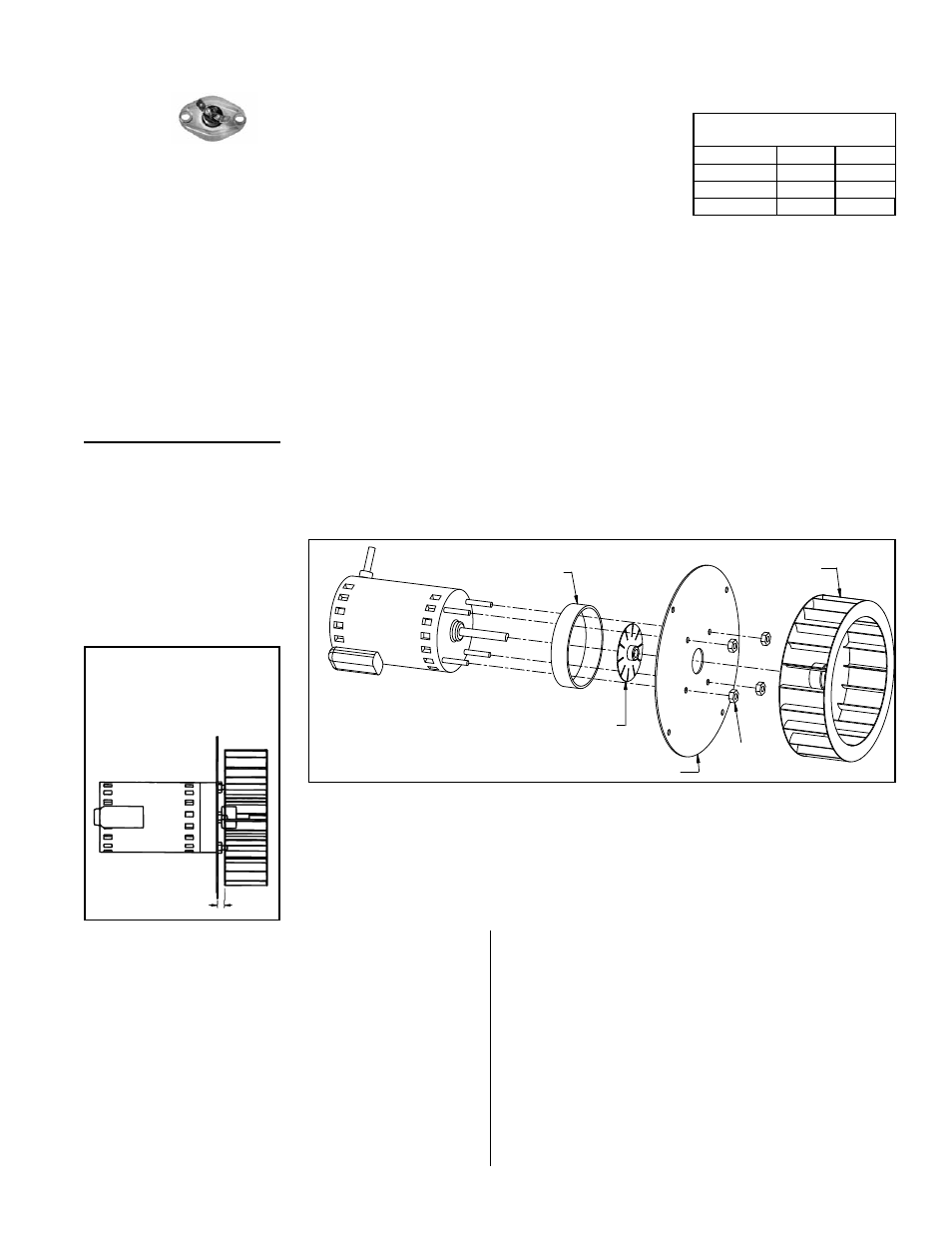
3.3.6 Venter Motor and
Wheel Assembly
Motor
Support Ring
Fan
Motor Mounting Plate
Nuts
(4)
Wheel
NOTE: Prior to 10/07,
included four spacers and
more narrow support ring.
FIGURE 7A - Venter
Motor and Wheel
Assembly
Complete Venter Motor
and Wheel Assembly
Size 150
, P/N 174010
Sizes 200, 250, 300,
P/N 162895
Sizes 350 and 400,
P/N 164542
Refer to Parts
Form P-CAUA
for components.
a) With a hex allen wrench, loosen the venter wheel setscrew. Slide the venter
wheel off the shaft.
b) Remove the four nuts holding the motor mounting plate. Remove the mounting
plate.
c) Slid over each bolt is a cylindrical spacer; remove the four spacers. Remove the
support ring.
d) Loosen the setscrew and remove the small fan blade.
FIGURE 7B - Spacing
between the venter
wheel and motor
mounting plate
5/16”
(8mm)
6. Re-assemble with the replacement venter motor
(
NOTE: Check the gasket on the motor mounting plate;
if deteriorated or torn, replace it.):
a) With the blade side closest to the motor (hub away
from motor), slide the small fan blade on to the
shaft. Position the blade so that it does not hit the
motor; tighten the set screw to the flat side of the
motor shaft.
b) Put a spacer over each bolt and slide the motor
support ring over all the bolts. Position the mounting
plate with the side with the gasket away from the
motor. Secure the plate with the nuts (hand tighten
with a nut driver; do not use a power tool). Rotate
the fan to check for clearance. If required, loosen
the set screw and adjust the position of the fan
blade.
c) With the "closed" side toward the motor, slide the
venter wheel over the end of the shaft. Position
the wheel with the spacing shown in
FIGURE 7B.
Tighten the set screw to the flat side of the motor
shaft. Check for proper balance. If the wheel is
damaged or does not turn properly, replace it.
7. Install the assembled venter motor and wheel. Follow
the wiring diagram to connect the venter wires. Close
the access panel.