Reznor CAUA Users Manual User Manual
Page 15
Form O-CAUA, P/N 164772 R7, Page 15
IMPORTANT: When using a multimeter to troubleshoot the 24 volt circuit, place the meter’s test leads into the 5 or 9
pin connectors located on the ignition control. Do not remove connectors or terminals from the electrical components.
Doing so can result in misinterpreted readings due to the ignition control board’s fault mode monitoring circuits.
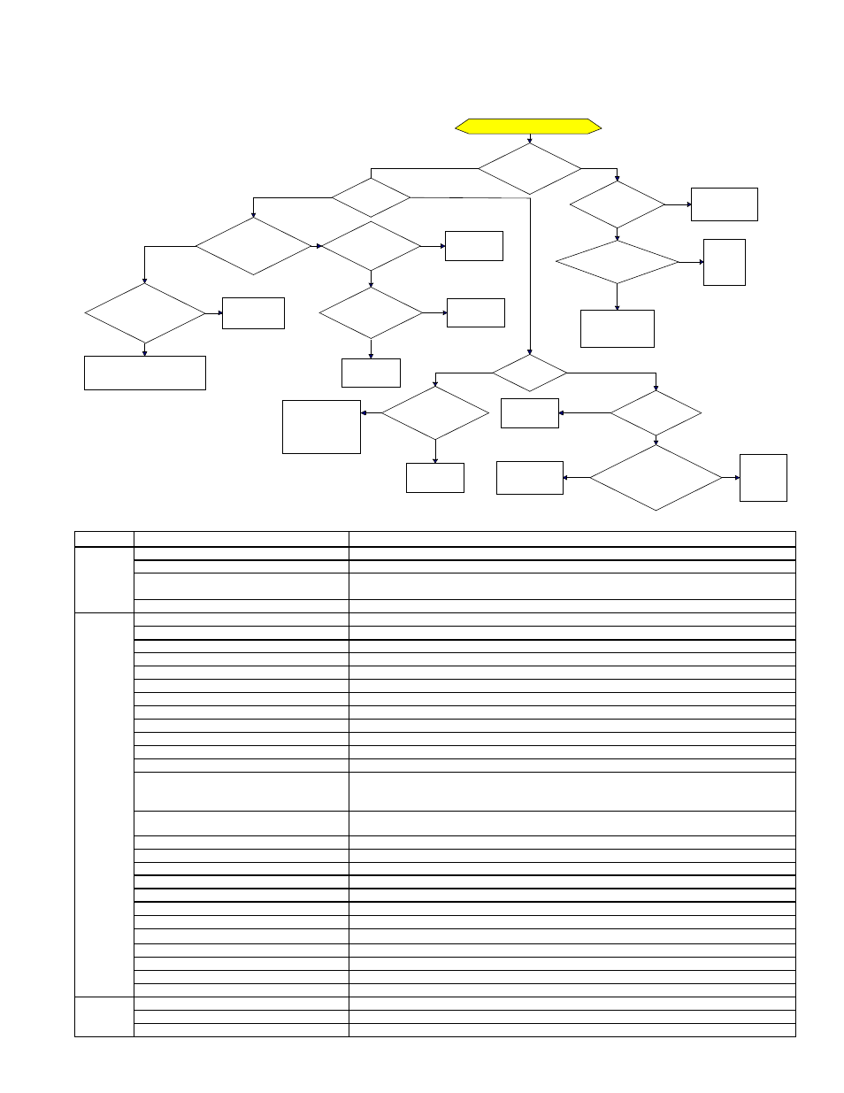
Trial for Ignition - Call for Heat
Is there a
spark across gap at
ignitor?
Does gas
ignite?
Is there minimum
flame current at the
flame sensor?
Is there
minimum flame current
at the control
module?
Replace control
module.
Check connections to flame
sensor and/or moisture in the
burner assembly.
Is the flame
sensor corroded?
Clean flame
sensor.
Is the sensor
located in flame
correctly?
Replace flame
sesnsor.
Reposition
flame sensor.
Is gas
flowing?
Is the ignitor
position correct in the
gas flow?
Check gas pressure
and supply voltage.
If either are low,
correct and repeat
startup.
Reposition
spark ignitor.
Is there
24VAC at the gas
valve?
Is there 24VAC
from gas valve output on
control module to
chassis?
Check wiring and
connections to
gas valve.
Replace
ignition
control
module.
Replace gas
valve.
Is there
spark voltage at
control?
Check high
voltage wire
continuity.
Is there 24V P1-2
to power control?
Replace
control
module.
Check wiring
and/or 24VAC
transformer output.
YES
NO
YES
NO
YES
NO
YES
NO
YES
NO
YES
NO
YES
NO
YES
NO
NO
YES
YES
NO
YES
NO
YES
NO
DSI Integrated Control Module (Circuit
Board) Trial Troubleshooting Flowchart
General Troubleshooting
PROBLEM PROBABLE CAUSE
REMEDY
Venter
motor will
not start
1. No power to unit.
1. Turn on power, check supply fuses or circuit breaker.
2. No 24 volt power to venter relay.
2. Turn up thermostat; check control transformer output.
3. Integrated ignition control module defective.
3. Replace integrated ignition control module. DO NOT ATTEMPT TO REPAIR CONTROL MODULE; IT
HAS NO FIELD REPLACEABLE COMPONENTS.
4. Defective venter motor.
4. Replace venter motor.
Burners will
not light
1. Manual valve not open.
1. Open manual valve.
2. Air in the gas line.
2. Bleed gas line.
3. Door switch open.
3. Close blower compartment door. If door is closed, replace switch.
4. Gas pressure is too high or too low.
4. Set supply pressure at 5" to 14" w.c. for natural gas and 11" to 14" w.c. for propane.
5. No Spark:
5.
a) Loose wire connections
a) Be certain all wire connections are solid.
b) Transformer failure
b) Be sure 24 volts is available.
c) Incorrect spark gap.
c) Maintain spark gap at 1/8".
d) Spark cable shorted to ground.
d) Replace worn or grounded spark cable.
e) Spark electrode shorted to ground
e) Replace if ceramic spark electrode is cracked or grounded.
f) Burners not grounded
f) Make certain ignition control module is grounded to the ignitor.
g) Ignition control module not grounded.
g) Make certain ignition control module is grounded to the furnace chassis.
h) Faulty integrated ignition control module
h) If 24-volt is available to the integrated ignition control module and all other causes have been eliminated,
replace module. DO NOT ATTEMPT TO REPAIR IGNITION CONTROL MODULE; IT HAS NO FIELD
REPLACEABLE COMPONENTS.
6. Lockout device interrupting control circuit by
above causes.
6. Reset lockout by interrupting control at the thermostat or main power.
7. Faulty combustion air proving switch.
7. Replace combustion air proving switch.
8. Main valve not operating.
8.
a) Defective valve
a) If 24 volt is measured at the valve connections and valve remains closed, replace valve.
b) Loose wire connections
b) Check and tighten all wiring connections.
9. Ignition module does not power the valve.
9.
a) Loose wire connections
a) Check and tighten all wiring connections.
b) Flame sensor grounded
b) Be certain flame sensor lead is not grounded or insulation/ceramic is not cracked. Replace as required.
c) Incorrect gas pressure
c) Set supply pressure at 5" to 14" w.c. for natural gas and 11" to 14" w.c. for propane.
d) Cracked ceramic at sensor
d) Replace sensor.
10. Flame rollout switch open
10.
a) Air blockage through the unit
a) Check for heat exchanger or vent pipe blockage.
b) Faulty flame rollout switch
b) Replace flame roll out switch.
Burners
cycle on
and off
1. Gas pressure is too high or too low.
1. Set supply pressure at 5" to 14" w.c. for natural gas and 11" to 14" w.c. for propane.
2. Burners not grounded
2. Make certain ignition control module is grounded to the ignitor.
3. Ignition control module not grounded.
3. Make certain ignition control module is grounded to the furnace chassis.