3 service procedures (cont'd) – Reznor CAUA Users Manual User Manual
Page 12
Form O-CAUA, Page 12
3.0 SERVICE - Control Location, Operation, and Service (cont'd)
3.3 Service Procedures (cont'd)
3.3.7 Transformer
Function: The 40VA transformer reduces the supply voltage to a 24-volt circuit in order
to operate the 24-volt controls.
Transformer Check (requires a volt meter): To verify the 24-volt circuit, check the
operation of the transformer. Set the thermostat to above room temperature. Using a
voltmeter, check the voltage between Terminal R on the thermostat terminal strip and
the ground terminal on the ignition controller. If there is no voltage in this circuit, the
transformer is not functioning. The service of a transformer is like that of a light bulb; it
is either good or bad and when bad, it must be replaced.
Service: If replacement of the transformer is necessary, do not substitute any other
transformer. Use replacement transformer IDENTICAL to the factory-installed models.
IMPORTANT NOTE: Do not short the "hot" side of the transformer to ground when
servicing the heater. Doing so will cause the transformer to fail.
40VA
Transformer
in the Heater
Electrical Box,
P/N 164328
40VA
Transformer
in the Optional
Mixing Box,
P/N 103497
3.3.8 Blower Motor and
Drive
Location/Function: The blower motor and blower are located in the blower compart-
ment at the bottom of the heater.
NOTE: The blower compartment door is equipped
with a safety switch. If the door is not closed, the heater will not operate.
The function of the motor and drive is to provide airflow through the heat exchanger
and supply air to the space. Model CAUA units are equipped either with a direct-drive
or a belt-drive blower and motor.
Size 150 and 200 heaters equipped with direct-drive have one 1HP blower motor. A
Size 150 has a 12-9 blower and a Size 200 has a 12-12 blower. Sizes 250-400 have
dual 1HP blower motors and dual 12-9 blowers.
Sizes 150-200 with belt-drive have a single motor and blower; sizes 250-400 have a
single motor and dual blowers. Motor ranges in size from 1/4 to 5 HP.
For information on how to adjust the blower speed, see Form I-CAUA, Paragraph 6.5.
CAUTION: An external duct system static pressure not within the limits
shown on the rating plate, or improper motor pulley or belt adjustment,
may overload the motor. See Hazard Levels, Page 2.
For information on replacing a belt, see Maintenance Section, Paragraph 2.2.1.
Function: The blower compartment door is equipped with a safety
switch. If the door is not closed securely, the heater will not operate.
Service: If it is determined that the blower compartment door switch
needs replacing, use only the factory-authorized replacement part
that is designed for use on this heater.
Door Switch, P/N 116023
Inlet Air Dampers
Location: Dampers and controls are located in the optional outside air/return air mix-
ing box. (Potentiometer may be remotely located.)
Function: Dampers operate in response to controls. See controls below and applica-
tion by option in
TABLE 5, page 14.
Service: Clean dampers and controls of dust or dirt.
2-Position Damper Motor
Function: The 2-position damper motor opens and closes the dampers. Damper posi-
tion is either on when the unit is operating or is determined by a two-position enthalpy
control.
Service: There is no service required on this motor other than external cleaning. If
the motor needs replaced, replace with an identical damper motor or damper motor
replacement kit.
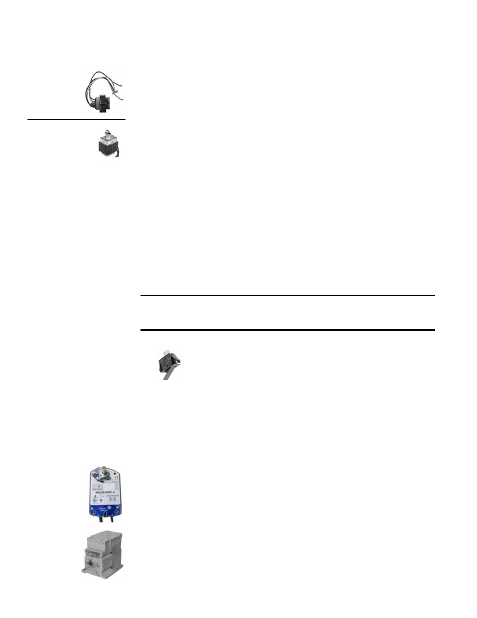
Modulating Damper Motor
Function: The modulating damper motor actuates the dampers in response to a
potentiometer or a mixed air controller. Outside air dampers close when the heater
shuts down.
Service: There is no service required on this motor other than external cleaning. If the
motor needs replaced, replace with an identical damper motor.
3.3.9 Blower
Compartment Door
Switch
3.3.10 Inlet Air Dampers
and Controls
2-Position
Damper
Motor
Modulating
Damper
Motor