3 service procedures (cont'd) – Reznor CAUA Users Manual User Manual
Page 10
Form O-CAUA, Page 10
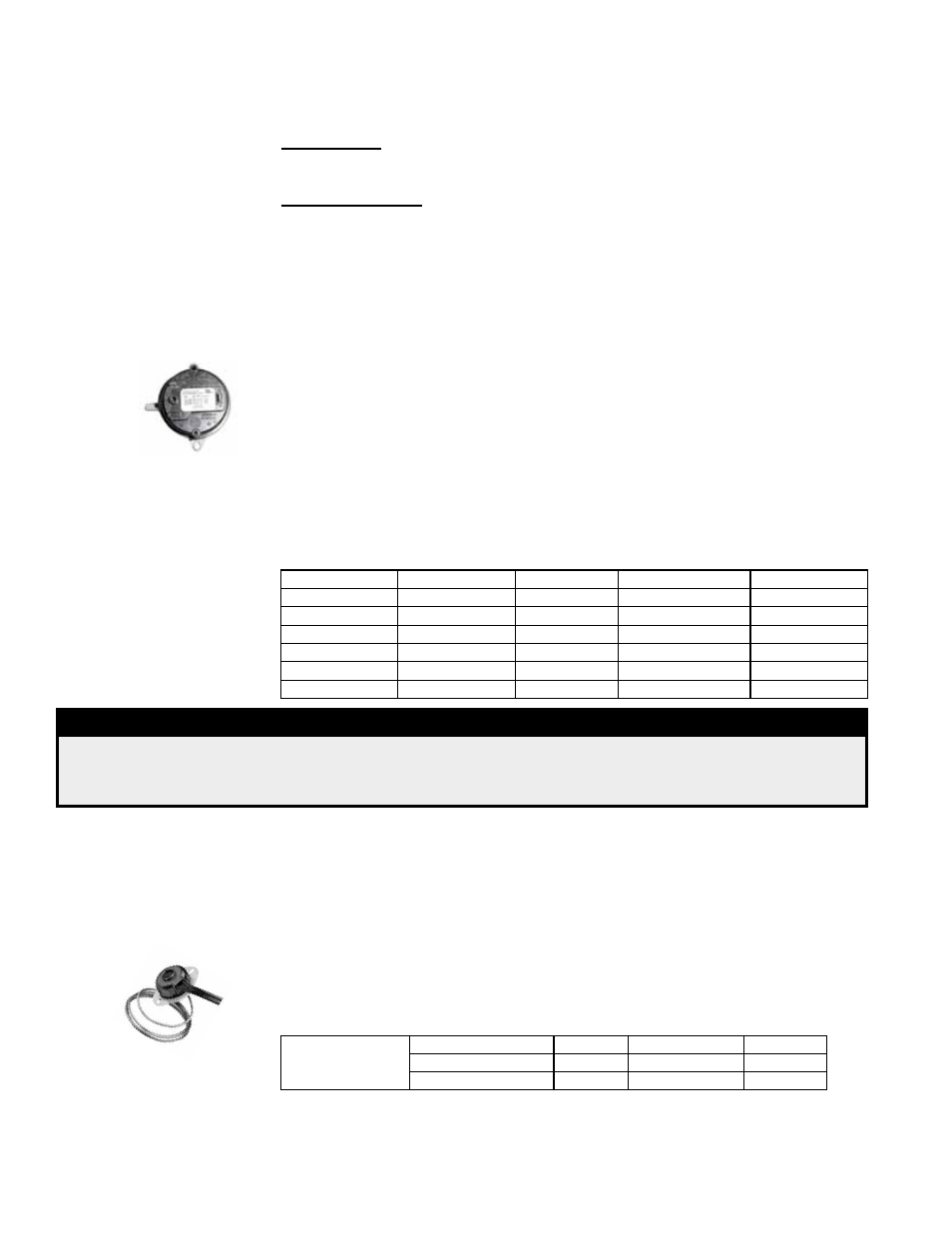
Service: Check the tubing that connects the pressure switch and the venter. If the tub-
ing is blocked or deteriorated, clean or replace. Be sure that the connections are tight.
If it is determined that the pressure switch needs replacing, use only the factory-autho-
rized replacement part that is designed for this heater. For location, see
FIGURE 4,
page 8.
Never bypass the pressure switch.
Function: The combustion air proving switch is a pressure sensitive switch that moni-
tors air pressure to ensure that proper combustion air flow is available. The switch is
single pole/double throw with the normally open contacts closing when a decreasing
pressure is sensed in the system.
On start-up when the heater is cold, the sensing pressure is at the most negative
level, and as the heater and flue system warm up, the sensing pressure becomes less
negative. After the system has reached equilibrium (about 20 minutes), the sensing
pressure levels off.
If a restriction or excessive flue length or turns cause the sensing pressure to be out-
side the switch setpoint, the pressure switch will function to shut off the main burners.
The main burners will remain off until the system has cooled and/or the flue system
resistance is reduced. The table below lists the approximate water column negative
pressure readings and switch setpoints for sea level operating conditions.
3.3.3 Combustion Air
Proving Switch
Function: The limit control is a temperature sensitive safety device that will shut down
the gas valve if a temperature above the setpoint is sensed. The limit control is an
automatic reset type with a capillary sensor. When the temperature drops below the
setpoint, the limit control deactivates allowing operation of the heater. The capillary
sensor extends across the heat exchanger section of the unit sensing the temperature
of the discharge air.
3.0 SERVICE
- Control
Location,
Operation,
and Service
(cont'd)
3.3 Service
Procedures
(cont'd)
3.3.2 Ignition System (cont'd)
Model Size
Start-Up Cold
Equilibrium
Setpoint “OFF”
Setpoint “ON”
150
1.45
1.05
.75
.90
200
1.50
1.05
.75
.90
250
1.55
1.10
.75
.90
300
1.60
1.15
.75
.90
350
1.30
1.05
.75
.90
400
1.20
1.00
.75
.90
DANGER
Safe operation requires proper venting flow. NEVER bypass the combustion air proving
switch or attempt to operate the unit without the venter running and the proper flow in the
vent system. Hazardous conditions could result. See Hazard Levels, Page 2.
TABLE 2 - Pressure
Switch Setpoints
(sea level)
3.3.4 Limit Control
TABLE 3 -
Limit Controls
For CAUA Sizes
P/N
Length
Setpoint
150, 200, 350, 400
148588
60" (1524mm) 270°F
250, 300
164792
54" (1372mm) 300°F
Service: If it is determined that the limit control needs replacing, use only the factory-
authorized replacement part that is designed for the size of heater (see P/N's above).
The limit control is accessible in the control compartment. The capillary sensor can
only be reached by removing the ductwork.
matically reset after one hour. Lockout may be manually reset by removing power from
the circuit board for more than one second or removing the call for heat for more than
one and less than 20 seconds.
Hard Lockout - If the circuit board detects a fault on the board, the status LED will be
de-energized, and the circuit board will lockout as long as the fault remains. A hard
lockout will automatically reset if the hardware fault clears.
Power Interruption - During a momentary power interruption or at voltage levels
below the minimum operating voltage (line voltage or low voltage) the ignition system
will self-recover without lockout when voltage returns to the operating range.
Power interruptions of less than 80mS shall not cause the circuit board to change
operating states. Power interruptions greater than 80mS may cause the circuit board
to interrupt the current operating cycle and re-start.
Pressure
Switch