Index references, General troubleshooting (cont'd) – Reznor CAUA Users Manual User Manual
Page 16
Form O-CAUA, Page 16
3.0 SERVICE - Control Location, Operation, and Service (cont'd)
www.ReznorHVAC.com; 1-800-695-1901
©2014 Reznor, LLC. All rights reserved.
Trademark Note: Reznor
®
is registered in at least the United States. All
other trademarks are the property of their respective owners.
0514 Form O-CAUA (Version A.3)
B
Belt Tension 3
Blower 3
Burner Maintenance 4
Burner Rack Removal 4
C
Combustion Air Proving
Switch 10
Condensate Drain 6
Control Locations 7
DSI Integrated Control
Module (Circuit Board)
Trial Troubleshooting
Flowchart 15
D
Damper Motor 12
Dampers and Controls 12
Door Switch 12
Drive 12
Ductstat 14
E
Enthalpy Sensor 13
F
Filter Cabinet 3
Filter Quantity and Sizes for
Mixing Box 3
Filters 3
Filters for Return Air Filter
Cabinet 3
Flame Rollout Switch 11
Flame Sensor 7
G
Gas Valve 4, 7
General 2
H
HAZARD INTENSITY
LEVELS 2
Cleaning the Heat Exchanger
6
I
Ignition Control Module 8
Ignition System 5, 6, 7, 8, 10
Ignition System Fault Mode 9
Ignitor 7
Inlet Base 3
L
Limit Control 10
M
Maintenance 2
Maintenance Procedures 3
Maintenance Schedule 2
Mixed Air Controller 13
Mixing Box 3
Motor 3, 12
P
Potentiometer 13
Pressure Switch Setpoints 10
R
Rating Plate 7
REFERENCES 17
Return Air Controller 13
S
SERVICE 6
Service Procedures 8, 10
Spark Gap 7
T
Transformer 12
Troubleshooting 14
V
Vent 6
Venter Motor and Wheel 6,
11
INDEX
REFERENCES
Description ............................................................................................... Form
Model CAUA
Installation Manual ......................................................... I-CAUA
Model ACU or Option C
Cased Cooling Coil Installation ..............I-CAUA-CC
Optional
Discharge Plenum Installation Instructions ..................I-CAUA-DP
Optional
Filter Cabinet Installation Instructions ..........................I-CAUA-FC
Optional
Inlet Air Mounting Base Installation Instructions .......... I-CAUA-IB
Optional
Mixing Box Installation Instructions ............................ I-CAUA-MB
Gas Conversion Instructions ................................................... CP-CAUA-GC
I
gnition Control Replacement Kit Instructions ...................... CP-CAUA-IGN
Replacement Parts ..............................................................................P-CAUA
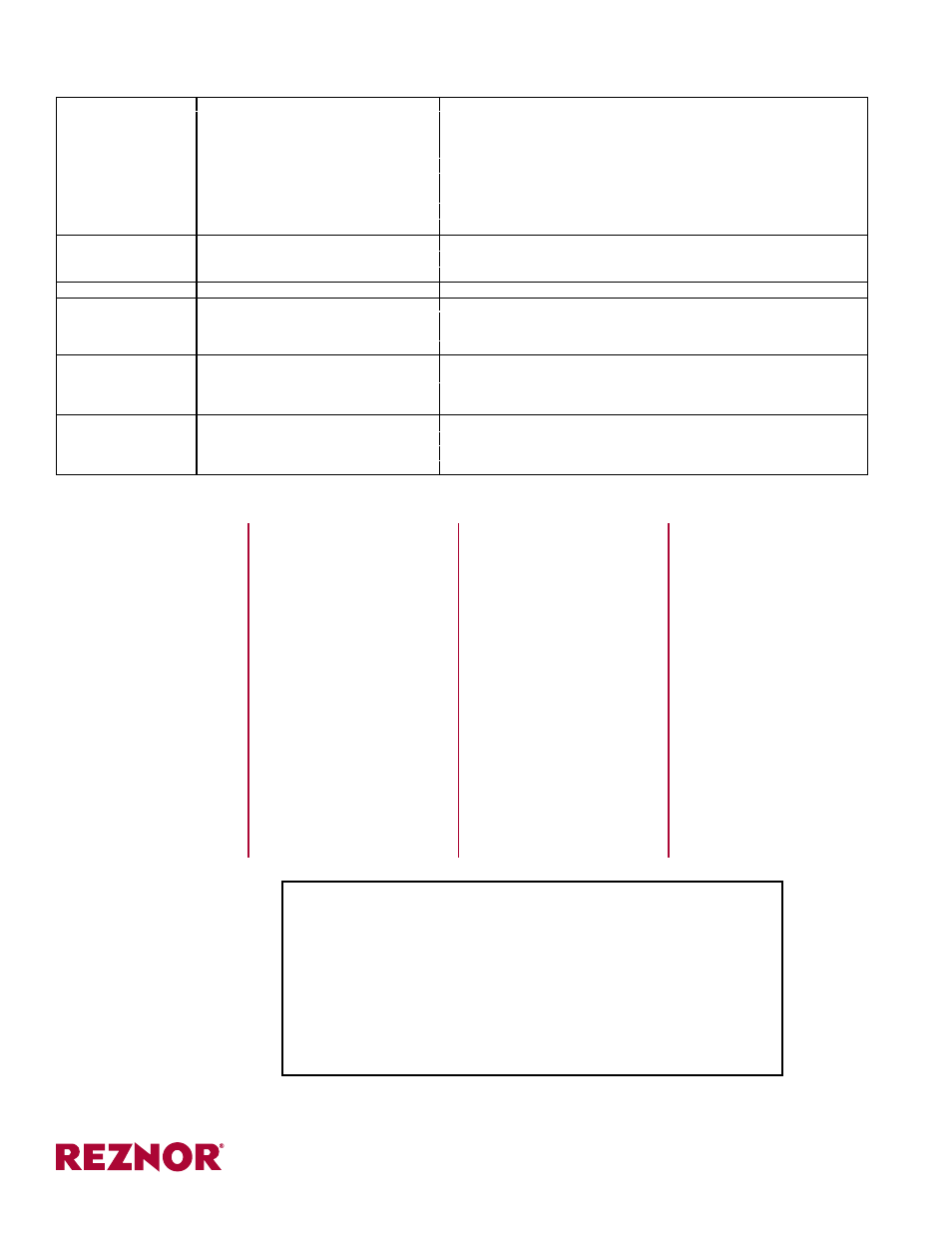
PROBLEM
PROBABLE CAUSE
REMEDY
Burners cycle on and off
(cont'd)
4. Faulty integrated ignition control module
4. If 24 volt is available to the integrated ignition control module and all other causes have
been eliminated, replace module.
DO NOT ATTEMPT TO REPAIR IGNITION CONTROL
MODULE; IT HAS NO FIELD REPLACEABLE COMPONENTS.
5. Faulty combustion air proving switch.
5. Replace combustion air proving switch.
6. Flame sensor grounded
6. Be certain flame sensor lead is not grounded or insulation or ceramic is not cracked.
Replace as required.
7. Cracked ceramic at sensor
7. Replace sensor
8. Incorrect polarity.
8. Reverse 115V line connections at ignition control module.
No heat (Heater Operating) 1. Incorrect manifold pressure or orifices.
1. Check manifold pressure (See Form I-CAUA, Paragraph 6.1).
2. Cycling on limit control.
2. Check airflow.
3. Improper thermostat location or adjustment.
3. See thermostat manufacturer's instructions.
Cold air delivered
1. Incorrect manifold pressure.
1. Check manifold pressure (See Form I-CAUA, Paragraph 6.1).
Blower motor will not
run
1. Circuit open.
1. Check wiring and connections.
2. Defective integrated ignition control
module (circuit board).
2. Replace module. DO NOT ATTEMPT TO REPAIR IGNITION CONTROL
MODULE; IT HAS NO FIELD REPLACEABLE COMPONENTS.
3. Defective motor.
3. Replace motor.
Blower motor turns
on and off while the
burner is operating
1. Motor overload device cycling on and
off. (See below.)
1. Check motor load against motor rating plate. Replace motor if needed.
2. 3-phase motor rotating in opposite
direction.
2. Interchange two legs of supply connections
Blower motor cuts out
on overload
1. Low or high supply voltage.
1. Correct electric supply.
2. Defective motor.
2. Replace motor.
3. Static pressure incompatibility.
3. Adjust blower speed or ductwork.
4. Defective bearing.
4. Replace motor.
General Troubleshooting (cont'd)
Forms are available to
download at
www.RezSpec.com.