3 service procedures (cont'd), 4 troubleshooting, Lights – Reznor CAUA Users Manual User Manual
Page 14
Form O-CAUA, Page 14
3.0 SERVICE - Control Location, Operation, and Service (cont'd)
3.3 Service Procedures (cont'd)
Mixing
Box
Option
Motor
Option
Control Option on
W.D.
Description
Operating
Mode
Application
GA1,
GA2,
GA3,
GA4,
GA5,
GA6,
GA7,
GA8,
and
GA9
GB2
None
2-Position
Damper Motor
Heating only
or Heating
and Cooling
When the unit is operating, the outside air damper is open.
GC3C
2-Position
Damper Motor
with 2-Position
Enthalpy
Control
Cooling only
To minimize cooling energy consumption and equipment cycling, when the sensor detects a low
enthalpy (heat content in a lb of air) in the outside air, the control will open the outside air damper.
When the control senses a high enthalpy in the outside air, the control will close the outside air
damper. Factory setpoint for opening the outside air damper is 75°F/40% humidity.
GC3C and GC4
Same as above (GC3C only) plus a delay based on return air temperature. Control delays the
opening of the outside air damper to provide faster cool down of the supply air.
GA4,
GA5,
GA6,
GA7,
GA8,
and
GA9
GB3
GC1A or GC1B
Modulating
Damper Motor
with Manual
Potentiometer
Mounted in
the Mixing
Box (GC1A)
or Remote
(GC1B)
Heating only
or Heating
and Cooling
To control mixture of inlet air, manually set the potentiometer to the desired minimum position of
the outside air damper. (See IMPORTANT NOTE left.)
GC1A or GC1B with
GC3A
Same as above (GC1A or GC1B only) plus in heating mode the dampers are modulated in
response to a control sensing the mixed inlet air temperature. The adjustable control has a range
of 0-100°F; factory setpoint is 35°F. (See IMPORTANT NOTE left.)
GC1A or GC1B with
GC4
Same as above (GC1A or GC1B only) plus a delay based on return air temperature. Control
delays the opening of the outside air damper to provide faster cool down (cooling mode) or warm
up (heating mode) of the supply air.
GC1A or GC1B with
both GC3A and GC4
Includes all of the control functions listed in this section - a potentiometer (GC1A or GC1B) with
both the mixed air controller (GC3A) and the delay (GC4).
GC3A
Modulating
Damper Motor
with Mixed Air
Controller
Heating only
Dampers are modulated in response to a control sensing the mixed inlet air temperature. The
adjustable control has a range of 0-100°F; factory setpoint is 35°F. (See IMPORTANT NOTE left.)
GC3A and GC4
Above plus a delay based on return air temperature. Control delays the opening of the outside air
damper to provide faster warm up of the supply air.
GB4
GC3B
Modulating
Damper Motor
with a Logic
Module and
Dual Setpoint
Modulating
Enthalpy
Control
Cooling and
Heating
In cooling mode, damper modulation is controlled by a modulating enthalpy control. With one
sensor measuring the enthalpy of the outside air and another sensing the return air, dampers
will modulate in response to the control to maintain the most economic mix in the inlet air
(normally set to maintain between 50-56°F). With two enthalpy setpoints, damper operation can
be interlocked with a time clock or other device to provide different mix depending on occupancy
or other determining factor. In the heating mode, damper modulation is controlled by a mixed air
temperature sensor. (See IMPORTANT NOTE left.)
GC3B and GC4
Above (GC3B only) plus a delay based on return air temperature. Control delays the opening of
the outside air damper to provide faster cool down (cooling mode) or warm up (heating mode) of
the supply air.
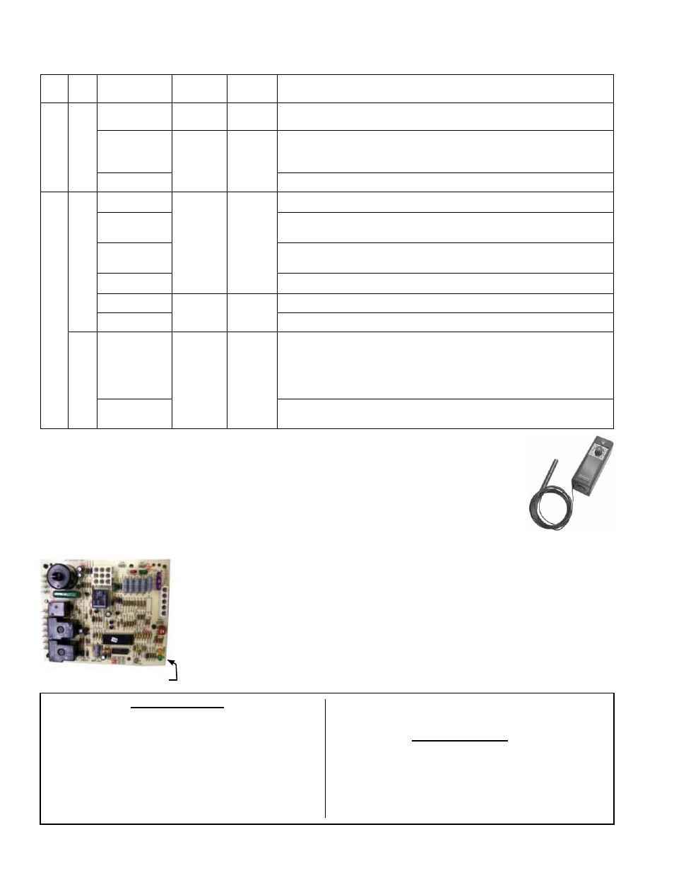
3.3.11 Ductstat used in
Makeup Air Gas Control
Option AG3 (available
only with Option AD4)
Function: The ductstat with attached capillary tube
senses the discharge air temperature and operates the
two stage valve to maintain the temperature within a
fixed differential of 2-1/2°F. Adjustable factory setting is
70°F.
Service: If the ductstat does not operate properly,
replace with an identical control.
Ductstat,
P/N 41700
The integrated circuit board monitors the operation of the heater and includes two
LED signal lights that indicate normal operation and various abnormal conditions. If
the heater fails to operate properly, check this signal to determine the cause and/or to
eliminate certain causes. Open the door panel to view the LED lights.
Do not attempt to repair the DSI integrated control module; the only field replaceable
component is the fuse.
Control Status - Green LED Codes
Steady ON .... Normal Operation, No call for heat
Fast Flash ..... Normal Operation, Call for heat
1 Flash .......... System Lockout, Failed to detect or sus-
tain flame
2 Flashes ...... Pressure Switch Did Not Close within 30
Seconds of Venter Motor
3 Flashes ...... High Limit Switch Open
4 Flashes ...... Pressure switch is closed before venter
motor is energized
Steady OFF .. Blown Fuse, No Power, or Defective
Board
Flame Status - Yellow LED Codes
Steady ON .... Flame is sensed
Slow Flash .... Weak flame (current below 1.0 micro-
amps ±50%)
Fast Flash ..... Undesired Flame (valve open and no call
for heat)
Lights
3.4 Troubleshooting
Check the Ignition Control Module - The integrated ignition control module monitors
the operation of the heater and includes LED signals that indicate normal operation
and various abnormal conditions. If the heater fails to operate properly, check this sig-
nal to determine the cause and/or to eliminate certain causes.