Warning – Reznor JS4BD (1ph) Unit Installation Manual User Manual
Page 5
5
• Provide power supply for the unit in accordance with the
unit wiring diagram, and the unit rating plate. Connect
the line-voltage leads to the terminals on the contactor
inside the control compartment.
• Use only copper wire for the line voltage power supply
to this unit as listed in Table 1. Use proper code agency
listed conduit and a conduit connector for connecting
the supply wires to the unit. Use of rain tight conduit
is recommended.
• 208/230 Volt units are shipped from the factory wired
for 230 volt operation. For 208V operation, remove the
lead from the transformer terminal marked 240V and
connect it to the terminal marked 208V.
• Optional equipment requiring connection to the power
or control circuits must be wired in strict accordance
of the NEC (ANSI/NFPA 70), applicable local codes,
and the instructions provided with the equipment.
copper Wire SiZe — aWg
(1% Voltage drop)
Supply Wire length-feet
Supply circuit
ampacity
200
150
100
50
6
8
10
14
15
4
6
8
12
20
4
6
8
10
25
4
4
6
10
30
3
4
6
8
35
3
4
6
8
40
2
3
4
6
45
2
3
4
6
50
2
3
4
6
55
1
2
3
4
60
Wire Size based on N.E.C. for 60° type copper conductors.
table 1. copper Wire Size
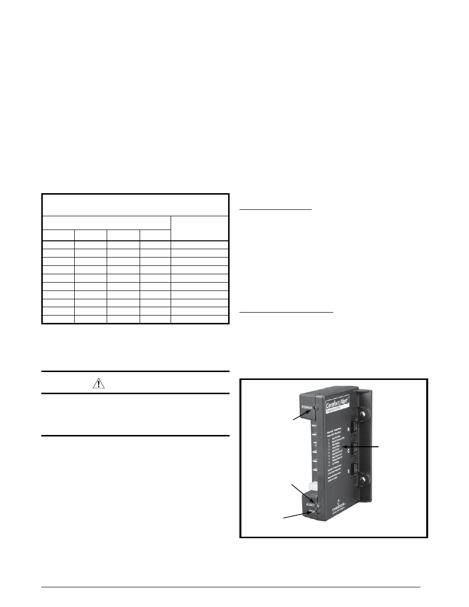
figure 2. comfort alert
tm
diagnostics module
POWER LED
(Green)
TRIP LED
(Red)
ALERT LED
(Yellow)
Diagnostics
Key
comfort alert
tm
diagnostics module
(Select models only)
The Comfort Alert
TM
Diagnostics Module (Figure 2) is a
breakthrough innovation that troubleshoots heat pump and
air conditioning system failures and accurately detects
the cause of electrical and system related failures without
any sensors. The module installs easily in the electrical
box of the outdoor unit near the compressor contactor. By
monitoring and analyzing data from the Copeland scroll
compressor and the thermostat demand, the module can
accurately detect the cause of electrical and system related
failures without any sensors. A flashing LED indicator
communicates the ALERT code and a diagnostic key is
also imprinted on the side of the module to quickly direct
the technician to the root cause of a problem.
note: This module does not provide safety protection!
The Comfort Alert
TM
Diagnostics Module is a monitoring
device and cannot control or shut down other devices.
24 VAC Power Wiring
The Comfort Alert
TM
module requires a constant nominal
24 VAC power supply. The module cannot be powered by
the c terminal on a defrost board or other control board
without experiencing nuisance alerts. note: The wiring
to the module’s r & c terminals must be routed directly
from the indoor unit or thermostat.
If the constant 24 VAC (r wire) is not present in the outdoor
unit, use one of the spare wires in the thermostat cable to
bring power to the module. Connect the other end of the
spare wire to r at the indoor unit or thermostat.
Thermostat Demand Wiring
The Comfort Alert
TM
module requires a thermostat demand
signal to operate properly. The thermostat demand
signal input (labeled y on the module), should always be
connected to the compressor contactor coil. note: When
the coil is energized, the demand signal input is 24 VAC.
When the coil is not energized, the demand signal input
should be less than 0.5 VAC.
grounding
Warning:
the unit cabinet must have an uninterrupted or
unbroken electrical ground to minimize personal
injury if an electrical fault should occur. do not
use gas piping as an electrical ground!
This unit must be electrically grounded in accordance
with local codes or, in the absence of local codes, with
the National Electrical Code (ANSI/NFPA 70) or the CSA
C22.1 Electrical Code. Use the grounding lug provided in
the control box for grounding the unit.