Horizontal vent terminal clearances, Figure 8b - horizontal vent terminal – Reznor X Option - Option - Installation - Power Venter User Manual
Page 9
Form I-X Venter, P/N 136958R1, Page 9
Structure
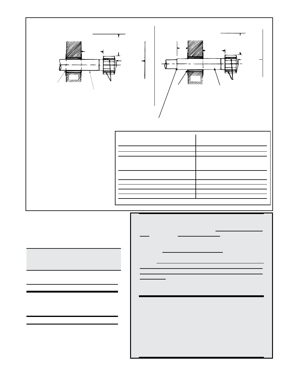
Min Clearances for Vent Termination
Location (all directions unless specified)
Forced air inlet within 10 ft (3.1m) 3 ft (0.9m) above
Combustion air inlet of another appliance 6 ft (1.8m)
Door, window, or gravity air inlet 4 ft (1.2m) horizontally
(any building opening)
4 ft (1.2m) below
1 ft (30cm) above
Electric meter, gas meter * and relief 4 ft (1.2m) horizontally
equipment
Gas regulator *
3 ft (0.9m)
Adjoining building or parapet
6 ft (1.8m)
Adjacent public walkways
7 ft (2.1m) above
Grade (ground level)
7 ft (2.1m) above
*Do not terminate the vent directly above a gas meter or service regulator.
6. Test Venter Operation
Turn on the electric and the gas. Following the lighting
instructions, light the heater. Test the unit for proper vent-
ing. With the building at the maximum negative pressure,
operate the heater at the normal input. Note and check the
flow direction at the relief opening of the drafthood. Room air
should be flowing into the relief opening.
DANGER: Do not put a heater into service
that does not properly exhaust flue gases to
the outside atmosphere. See Hazard Levels,
page 1.
Venter installation is complete.
Keep this booklet for future
reference. Replacement parts are on page 8.
DANGER: The gas burner in this gas-fired equip-
ment is designed and equipped to provide safe
and economically controlled complete combus-
tion. However, if the installation does not permit
the burner to receive the proper supply of combus-
tion air, complete combustion may not occur. The
result is incomplete combustion which produces
carbon monoxide, a poisonous gas that can cause
death. Safe operation of indirect-fired gas burning
equipment requires a properly operating vent sys-
tem which vents all flue products to the outside at-
mosphere. FAILURE TO PROVIDE PROPER VENT-
ING WILL RESULT IN A HEALTH HAZARD WHICH
COULD CAUSE SERIOUS PERSONAL INJURY OR
DEATH.
Always comply with the combustion air require-
ments in the installation codes and instructions.
Combustion air at the burner should be regulated
only by manufacturer-provided equipment. NEVER
RESTRICT OR OTHERWISE ALTER THE SUPPLY
OF COMBUSTION AIR TO ANY HEATER. Indoor
units installed in a confined space must be sup-
plied with air for combustion as required by Code
and in the heater installation manual. MAINTAIN
THE VENT SYSTEM IN STRUCTURALLY SOUND
AND PROPERLY OPERATING CONDITION.
FOR YOUR SAFETY
WARNING: The use and storage of
gasoline or other flammable vapors
and liquids in open containers in the
vicinity of this appliance is hazardous.
If you smell gas:
1. Open windows.
2. Don't touch electrical switches.
3. Extinguish any open flame.
4. Immediately call your gas supplier.
Roof or Building Overhang
3 (1M) minimum
18
(457mm)
minimum
6 (2M)
minimum
Wall
Parapet or
Adjoining Building
Approved clearance
thimble for single-wall
vent pipe is required
when flue pipe extends
through combustible
materials.
Note position of vent
cap openings.
Pitch flue pipe down toward outlet
1/4 per foot for condensate drainage.
(NOTE: Applies to entire horizontal
vent run.)
Adjoining Building
Parapet or
Roof or Building Overhang
6 (2M)
minimum
3 (1M) minimum
18
(457mm)
minimum
Wall
Approved clearance
thimble for single-wall
vent pipe is required
when flue pipe extends
through combustible
materials. Follow
the requirements
of the double-wall
pipe manufacturer.
Pitch flue pipe down toward
outlet 1/4 per foot for con-
densate drainage.
(NOTE: Applies to entire
horizontal vent run.)
Note position of
vent cap openings.
6 (152mm) minimum
Follow instructions on page 6 to join single
and double-wall pipe and to seal the connection.
Single-Wall Vent Run and Double-Wall Terminal End
Single-Wall Vent Run and
Single-Wall Terminal End
Horizontal Vent Terminal
Clearances
A vent cap is required. Maintain a clear-
ance of 18" from the wall to the vent ter-
minal cap for stability under wind condi-
tions. The location of the termination of
the horizontal vent system must be in
accordance with National Fuel Gas Code
Z223.1. Required minimum clearances
are listed on the right.
Products of combustion can cause dis-
coloration of some building finishes
and deterioration of masonry materials.
Applying a clear silicone sealant that is
normally used to protect concrete drive-
ways can protect masonry materials.
If discoloration is an esthetic problem,
relocate the vent or install a vertical vent.
If the vent terminal is to be installed near
ground level, position it at least six inches
above maximum anticipated snow depth.
Figure 8B - Horizontal Vent Terminal