Installation instructions (cont'd) – Reznor X Option - Option - Installation - Power Venter User Manual
Page 6
Form I-X Venter, P/N 136958R1, Page 6
5. Install Vent Pipe -- Venting must be in accordance with the National Fuel Gas Code
Z223.1 or CAN/CGA B149.1 and B149.2, Installation Code for Gas Burning Appliances
and Equipment, and all local codes. Local requirements supersede national require-
ments.
With the power venter installed, these heaters are designed to operate safely and
efficiently with either a horizontal or vertical vent. (Horizontal vent run is recommended
for maximum fuel savings.) Use either vent pipe approved for a Category III heater or
appropriately sealed single-wall pipe. Or, if at least half of the equivalent length of the
vent system is vertical, vent pipe approved for a Category I heater may be used. A vent
cap of a type approved for use with this heater is required. Comply with the specific
requirements and instructions in the following paragraphs.
If this heater is replacing an existing heater, be sure that the vent is sized properly for
the heater being installed. A properly sized vent system is required for safe operation
of this heater. An improperly sized vent system can cause unsafe conditions and/or
create condensation.
Venting requirements change with the addition of the power venter. Acceptable vent
size and lengths are shown below.
a. Vent Pipe - If installed with a horizontal vent run, use either vent pipe approved for
a Category III heater or appropriately sealed 26-gauge galvanized steel or equiva-
lent single-wall pipe. If at least half of the equivalent length of the vent system is
vertical, vent pipe approved for a Category I heater may be used. Single-wall pipe
or double-wall (Type B) vent pipe are suitable for use with a Category I heater.
Use only one of the flue pipe diameter(s) listed in the Maximum Permissible Vent
Length Table below for the heater size being installed.
Additional NOTES:
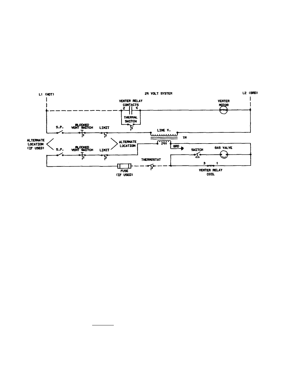
1) Typical wiring for a unit equipped with a standing match lit pilot. Check wiring diagram with the unit or in
FIGURE 6A for a heater with spark ignition.
2) Fuse required on C.G.A. units manufactured prior to 10/89.
3) Blocked vent switch is standard on all units manufactured after 4/91.
4) Thermal switch is standard on optional venters manufactured beginning 4/93.
FIGURE 6B - Typical Wiring Diagram for Unit with Optional Power Venter (24 volt control system)
using a pressure switch replacing the previously used sail switch (power venter options
manufactured beginning 8/2012) and a Match-Lit Pilot
NOTES:
Model Series X, CX, XE, and CXE furnaces manufactured beginning 10/03 are
equipped with a spark pilot.
Model Series X, CX, XE, and CXE furnaces manufactured beginning 4/91 are
equipped with a blocked vent switch.
Model Series X, CX, XE and CXE units manufactured prior to 4/91 and Model XL,
CXL, CXLB, and CXLB Series unit heaters are not equipped with a blocked vent
switch.
PRESSURE
Installation
Instructions
(cont'd)
4. Electrical Wiring
(cont'd)