Venter operation, Installation instructions, Venter sub-assembly dimensions - inches (mm) – Reznor X Option - Option - Installation - Power Venter User Manual
Page 3: Venter housing
Form I-X Venter, P/N 136958R1, Page 3
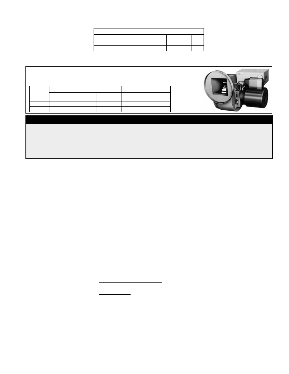
Blower System
Venter Sub-Assembly
Dimensions - inches (mm)
FIGURE 2 - Venter
Sub-Assembly
Venters have a centrifugal blower with forward curved blades. Blowers are statically
and dynamically balanced.
CFM (70°F)
Static Pressure 0.00 0.25 0.50 0.75 1.00 1.25
Sizes 30-300
220
205
190
160
75
--
Sizes 350-400
265
255
245
240 220 185
Venter Housing
Blower and motor are enclosed in corrosion resistant steel housing, finished in baked
enamel.
Venter
Sub-Assy
for Sizes
Overall
Connections (I.D.)
Height
Width
Length
Adapter
Vent Pipe
30-300
7-1/2 (191)
10 (254) 7-1/16 (179) 4-1/16 (103) 4-1/16 (103)
350-400 9-3/8 (238) 10-5/8 (270) 8-1/2 (216)
6 (152)
6 (152)
DANGER
This power venter is to be installed by a qualified agency in accordance with these
instructions and in compliance with all codes and requirements of authorities having
jurisdiction. Failure to follow instructions could result in death, serious injury, and/or
property damage. The qualified agency performing this work assumes responsibility for
this installation.
Venter Operation
Before beginning the actual installation, it will be helpful to understand the fundamental
operation and sequencing of the power venter.
The venter's relay coil is wired in series with the thermostat. When the thermostat calls
for heat, the thermostat contacts close the circuit which, after a delay of approximately
15 - 60 seconds, starts the venter. When the venter starts, air from the venter blower
closes the airflow (sail) switch that is built into the venter. The closing of the airflow
switch completes the electric circuit to the burner controls, opening the gas valve.
When the thermostat is satisfied, the thermostat closes the gas valve. A thermal switch
permits post-purge venter blower operation to prevent unnecessary lockouts by the
temperature-sensitive blocked vent system on the heater. When the venter blower
stops, the airflow switch resets to the open position.
Installation
Instructions
Verify that the venter sub-assembly and the venter flue adapter are compatible with
the heater being serviced. Check Model, Size, and Voltage. The following parts are
required.
Supplied
• Venter Flue Adapter
• Venter Sub-Assembly
Field Supplied
For heater with a Horizontal Flue - Six #10 sheetmetal screws
For heater with a Vertical Flue - Nine #10 sheetmetal screws and a vent pipe
elbow (4" or 6" depending on heater model and size)
All Installations - Wiring and accessories including 18 gauge wire for control (24V)
wiring, 14 gauge wire for line voltage, flexible conduit for both control and line volt-
age wires, wire connectors, and conduit connectors.
1. If the heater is installed, turn off the gas and the electric.
2. Install the Venter Flue Adapter (Refer to Figure 3) -- The adapter has a "large"
either oblong or round collar ("A") that attaches to the flue collar on the heater and a
smaller collar ("B") for attaching directly to the venter (horizontal flue) or to a vent pipe
(vertical flue).
Position the adapter with the smaller round (4" or 6" collar) toward the top (horizontal
flue) or front (vertical flue) of the heater and fit the larger collar over the heater flue
collar.