Reznor X Option - Option - Installation - Power Venter User Manual
Page 7
Form I-X Venter, P/N 136958R1, Page 7
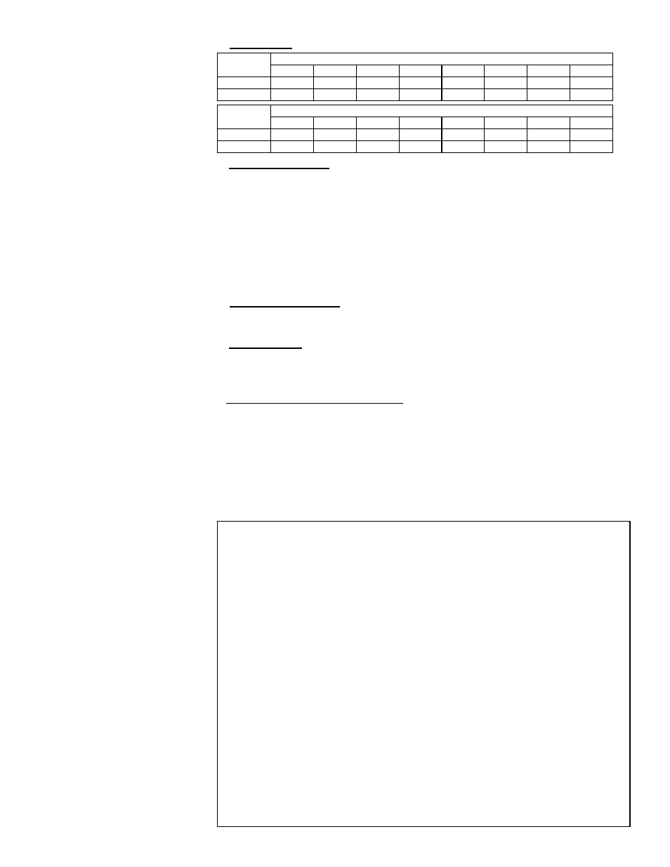
*Reduce the vent pipe
lengths as follows for each
item: 45
o
Elbow - 7ft (2M);
90
o
Elbow - 15ft (4.5M);
Vent Cap - 10 ft (3M).
** If the venter outlet is 4"
(102mm), connect a taper-
type "enlarger" to the ven-
ter outlet when installing
6" (152mm) vent pipe.
b. Vent Length - Minimum vent length is 5 feet.
Vent
Diameter
Maximum Length* (ft) by Heater Size
30-150
175
200
225
250
300
350
400
4"
100
75
50
35
30
15
--
--
6"
--
--
--
--
100**
100**
100
92
Vent
Diameter
Maximum Length* (M) by Heater Size
30-150
175
200
225
250
300
350
400
102mm
30
23
15
11
9
4.5
--
--
152mm
--
--
--
--
30**
30**
30
28
c. Vent System Joints - Vent system joints depend on the installation and the type of
pipe being used.
If installed as a Category III heater (required if more than half of the equivalent
length of the vent system is horizontal), use
vent pipe specifically approved for
Category III vent systems. Follow the pipe manufacturer's instructions for proper
sealing.
If installed with a Category I vent system (allowed only if at least half of the
equivalent length of the vent system is vertical), use at least two non-corrosive
screws per vent pipe joint on single-wall pipe or follow the pipe manufacturer's
instructions for joining double-wall pipe.
d. Vent System Support - Lateral runs should be supported every six feet using a
non-combustible material, such as strap steel or chain. Do not rely on the heater
for support of either horizontal or vertical vent pipe.
e. Condensation - Any length of single-wall vent pipe exposed to cold air or run
through an unheated area or an area with an ambient temperature of 45°F or
less must be insulated along its entire length with a minimum of 1/2" foil-faced
fiberglass, 1-1/2# density insulation.
f. Vent Terminal (Pipe and Vent Cap) - The vent cap must be the same size as the
vent pipe (vent pipe is either 4" or 6" diameter). For optimum stability under wind
conditions, use a Reznor
®
vent cap.
See the illustrations in
FIGURES 7A and 7B for requirements of vertical and
horizontal vent termination. The vent terminal pipe may be either single-wall or
double-wall (Type B). (Check local codes for double-wall terminal requirement.) If
double-wall pipe is used in the vent terminal with a single-wall vent run, follow the
instructions below to attach the vent cap and to connect the double-wall pipe to the
single-wall vent pipe run.
Instructions to attach VENT CAP to DOUBLE WALL (Type B) VENT TERMINAL
PIPE
Look for the "flow" arrow on the vent pipe. Attach the vent cap to the "exhaust" end
of the double wall pipe.
1) Slide the vent cap inside the pipe.
2) Drill a hole through the pipe and the vent cap. (Hole should be slightly smaller
than the sheet metal screw being used.) Using a 3/4" long sheet metal screw,
attach the cap to the pipe.
3) Repeat Step 2) drilling and inserting two additional screws evenly spaced (120°
apart) around the pipe.
Instructions to connect a SINGLE WALL VENT RUN to a DOUBLE WALL (Type
B) VENT TERMINAL PIPE:
1) Slide the single wall pipe inside the inner wall of the double-wall terminal pipe.
2) Drill a hole through both walls of the double wall pipe and the single wall pipe.
(Hole should be slightly smaller than the sheet metal screws being used.)
Using a 3/4" long sheet metal screw, attach the two pieces of pipe. Do not
overtighten.
3) Repeat Step 2) drilling and inserting two additional screws evenly spaced (120
o
apart) around the pipe.
4) To seal the annular opening (the gap between the single and double wall pipe),
run a large bead of silicone sealant in the opening. The bead of sealant must
be large enough to seal the opening, but it is not necessary to fill the full vol-
ume of the annular area.