Installation instructions (cont'd), Correct installation – Reznor X Option - Option - Installation - Power Venter User Manual
Page 4
Form I-X Venter, P/N 136958R1, Page 4
To attach the adapter, hold it in place and select the location for drilling a 1/8" diameter
hole (No. 30 drill) through the connecting overlap of the heater flue and the adapter
collar.
For an oblong horizontal flue, drill the first hole on either side of the top.
For a round horizontal flue, drill the first hole in the top portion of the circle.
For an oblong vertical flue, drill the first hole on either "end" of the side toward
the front of the heater.
For a round vertical flue, drill the first hole on the portion of the circle toward the
front of the heater.
Insert a #10 sheetmetal screw. Drill two more holes -- for an
oblong flue, drill a hole in
the opposite edge of the same side as the first hole, and one in the middle of the oppo-
site side; and for a
round flue, space the three holes approximately equal distances
apart. Attach with sheetmetal screws.
3. Install the Venter Sub-Assembly -- The venter sub-assembly is assembled and
wired at the factory. It includes the blower, motor, capacitor, pressure switch, thermal
switch, and junction box. Select and follow the appropriate instructions.
Heater with a Horizontal Flue (FIGURE 4) -- Position the venter sub-assembly on the
flue adapter. The venter discharge outlet (vent connection) must be pointing in a direc-
tion from horizontal to vertical.
Do not position the venter with the discharge outlet
(vent connection) in a direction below horizontal.
Drill
Drill
Drill
Drill
Drill
Drill
Adapter
Flue
Collar
A
B
Angle Range of
Installation
V
ertical
Horizont
al
FIGURE 5
- Install
an elbow before
attaching the
venter sub-
assembly on a
heater with a
vertical (top) flue.
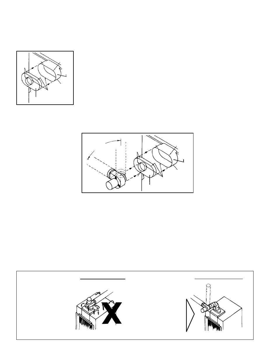
Incorrect Installation
Correct Installation
200-350°Fair entering
motor housing
Spillage from
relief opening
Horizontal
or Vertical
Exhaust
80-100°F entering
motor housing
Install an elbow
between the adapter
and the venter inlet
when top flue
connection is used.
Attach adapter to flue collar
and install a 4 to 6elbow
between adapter and venter.
Installation
Instructions
(cont'd)
Drill
Drill
Drill
Drill
Drill
Drill
Flue
Collar
Adapter
A
B
FIGURE 3 - Install Flue
Adapter
FIGURE 4 - Install
Venter Sub-Assembly in
a Horizontal Flue
Holding the venter sub-assembly in position, drill a hole through the connecting over-
lap in the top portion of the venter sub-assembly and the venter adapter. Insert a #10
sheetmetal screw. Drill two more holes approximately equal distances apart. Attach
with sheetmetal screws.
Heater with a Vertical (top ) Flue (FIGURE 5) -- Using sheetmetal screws, attach a
vent pipe elbow as shown in
FIGURE 5. Position the venter sub-assembly on the vent
pipe elbow. The venter discharge outlet (vent connection) must be pointing in a direc-
tion from horizontal to vertical.
Do not position the venter with the discharge outlet
(vent connection) in a direction below horizontal.
Holding the venter sub-assembly in position, drill a hole through the connecting over-
lap in the top portion of the venter sub-assembly and the vent pipe elbow. Insert a #10
sheetmetal screw. Drill two more holes approximately equal distances apart. Attach
with sheetmetal screws.