Installation instructions (cont'd) – Reznor X Option - Option - Installation - Power Venter User Manual
Page 8
Form I-X Venter, P/N 136958R1, Page 8
WARNING
Units installed in multiples require individual vent pipe runs and
vent caps. Manifolding of vent runs is not permitted
5. Install Vent Pipe (cont'd)
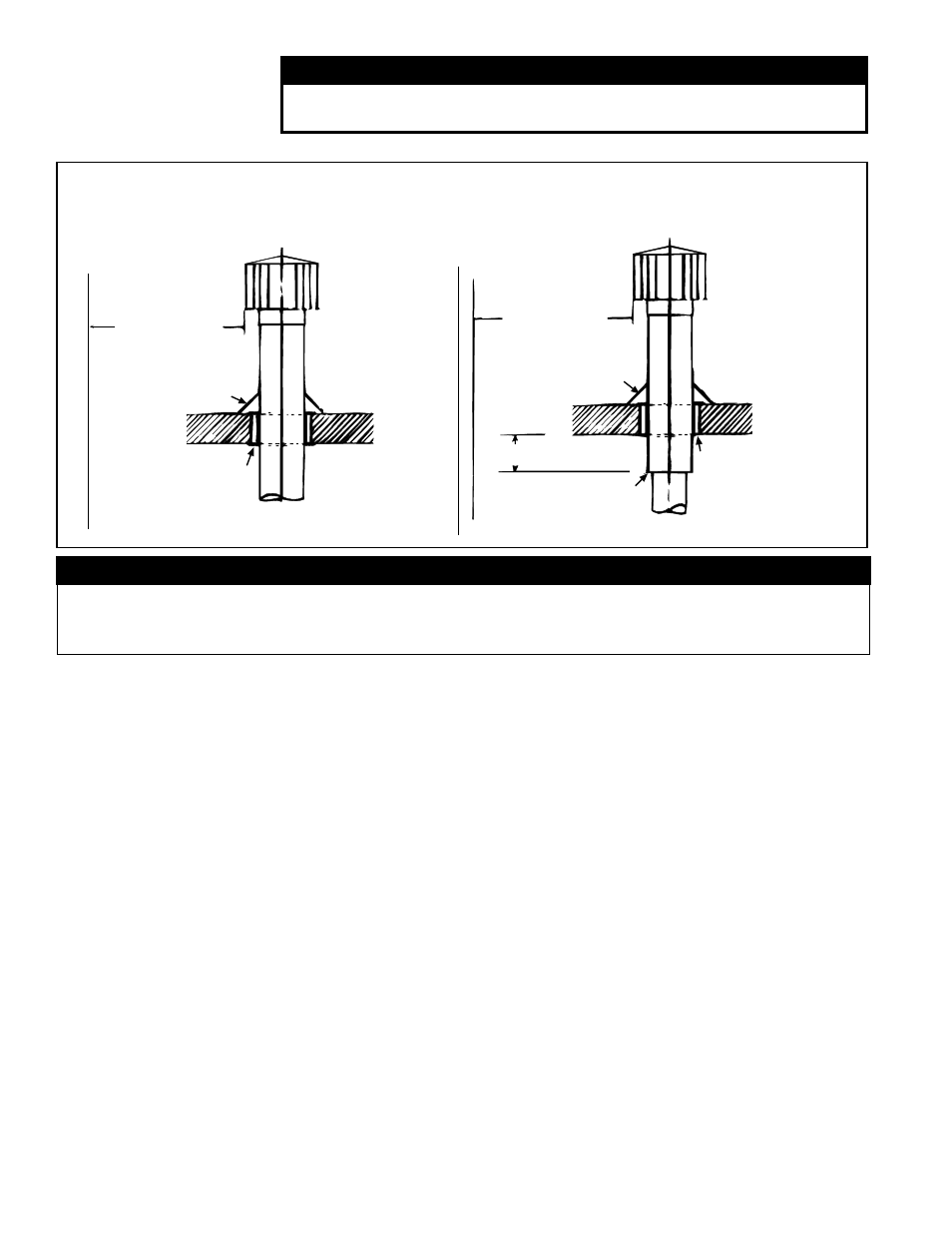
Figure 8A - Vertical Vent Terminal
WARNING
Vent terminal arrangements illustrated are applicable only to units with a power venter.
Horizontal vent termination requires a power venter. DO NOT use horizontal vent with
gravity venting.
6 (2M) minimum
6 (2M) minimum
Approved clearance thimble
for single-wall vent pipe is
required when flue pipe
extends through
combustible materials.
Parapet or Adjoining Building
Vertical flue extension to
be 6 (152mm) higher than
anticipated snow depth but
no less than 2 feet (610mm)
above the roof.
Vertical pipe extension
must be insulated.
Roof Flashing
Roof - pitched
from 0 to 45°
Vertical flue extension
to be 6 (152mm) higher
than anticipated snow
depth but no less than
2 feet (610mm) above the
roof.
6 (152mm) minimum
Roof Flashing
Roof - pitched
from 0 to 45°
Approved clearance thimble
for single-wall vent pipe is
required when flue pipe extends
through combustible materials.
Follow the requirements of the
double-wall pipe manufacturer.
Follow instructions on page 6
to join single and double-wall
pipe and to seal the connection.
Parapet or Adjoining Building
Single-Wall Vent Run and
Single-Wall Terminal End
Single-Wall Vent Run and
Double-Wall Terminal End
Installation
Instructions
(cont'd)