PRG DMX Reference Guide 5.4 User Manual
Page 87
DMX512 REFERENCE GUIDE
79
Step
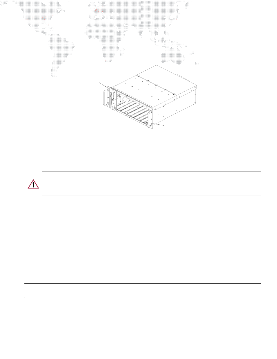
5. Configure Modular Rack.
Configure APS6 and/or C3 modules in SixPack chassis with regard to port assignments for each Smart
Repeater unit. In other words, if there is a VL6 luminaire connected to the first output on a Smart Repeater
unit, an APS6 module should be installed in the first slot of the chassis connected to that Smart Repeater
unit so that it receives power from an arc power supply module.
Figure 3-33: SixPack Chassis
Step
6. Configure SPC-36 controller.
If an SPC-36 controller is used to remotely start VL6 luminaire lamps or control C3 modules, it is normally
installed into the topmost position of the modular rack. However, it can be removed from the modular rack
and installed elsewhere as long as it is still directly connected to a SixPack chassis.
CAUTION:
It is preferable to connect the SPC-36 controller’s S200 AC & DATA input to a SERIES 200
POWER OUT connector on modular rack’s breaker panel and not to a separate power source. This prevents
ground-loop problems when modular rack and SPC-36 controllers are on separate power sources. DO NOT
share separate grounds.
a.
For APS6 modules, make sure that the PSET or DCV jumper is set to DCV mode for correct wattage so
that it can correctly respond to the SPC-36 controller. Refer to
"Configure APS6 modules. (There are
b.
Attach the SPC-36 controller cables to each of the control inputs on the SixPack chassis installed in the
modular rack.
c.
Set SPC-36 controller thumbwheel address. One SPC-36 controller can control up to 36 modules.
Step
7. Hang luminaires.
a.
Determine hanging orientation of luminaires (refer to
"Luminaire Orientation and Placement"
page 53). Ensure the following:
1)
Pipe for mounting luminaires is between 1 and 2 inches (25.40 to 50.80 mm) in outer diameter.
2)
The structure is secure and capable of supporting total luminaire load.
3)
Sufficient clearance space is provided for each luminaire.
Note: It is recommended that all luminaire input connectors be orientated facing stage left, or at least in the same
direction by hanging position.
b.
Make sure that double truss hook or clamp (VL7) is oriented and bolted to pan tube correctly.
Luminaire addresses are usually decided upon prior to the set-up of equipment. The lighting plot may
contain this information.
Port 6
Port 1