Aps 6 – PRG VL6C+ User Manual
Page 34
26
VL6C+ ™ SPOT LUMINAIRE USER MANUAL
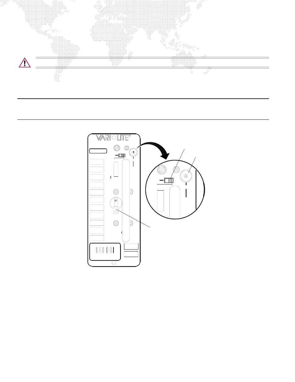
Configure APS6 module(s):
Lamp power for the VL6C+ Spot Luminaire is provided by an APS6 power supply module installed in a Series 300
Modular Rack.
CAUTION:
Do not change mode or power setting with power applied to module.
Step
1. At face of APS6 module(s), set rotary power switch to the 700W position (Figure 2-10).
Step
2. Set mode switch to PSET for manual operation.
Step
3. Apply power to lamp by moving circuit breaker switch to the ON position.
Note: The PSET (Preset) mode enables manual control of the module. This is the normal mode of operation. The DCV
(Dimmer Control Voltage) mode operates the module with 0-10Vdc control input. This mode is only required when
using an SPC-36 controller to remotely control modules from a console.
Figure 2-10: APS6 Module
Power Up the Luminaire:
Proceed to
on page 28 for further operating instructions.
PRG
PRG
ARC
7257730
MODULE
BREAKER IS OFF
BEFORE
SELECTING POWER.
OFF BEFORE REM
WARNING:UNIT MU URNED
DO NOT UNPLUG H
ENSURE THAT
O
O
A
S300U-06
DCV
PSET
DCV
SHORT
STATUS
IPRES
MODE
3-XXXW
O
2-700W
1-625W
0-400W
POWER
3
1
2
APS 6
DCV
HORT
DCV
PSET
AC
ON
0-400W
2-700W
1-625W
3-XXXW
0
POWER
23
1
AC
ON
0
Power Switch
Mode Switch
Circuit Breaker Switch