Operation overview, External power and data configuration – PRG VL6C+ User Manual
Page 19
VL6C+ ™ SPOT LUMINAIRE USER MANUAL
11
OPERATION OVERVIEW
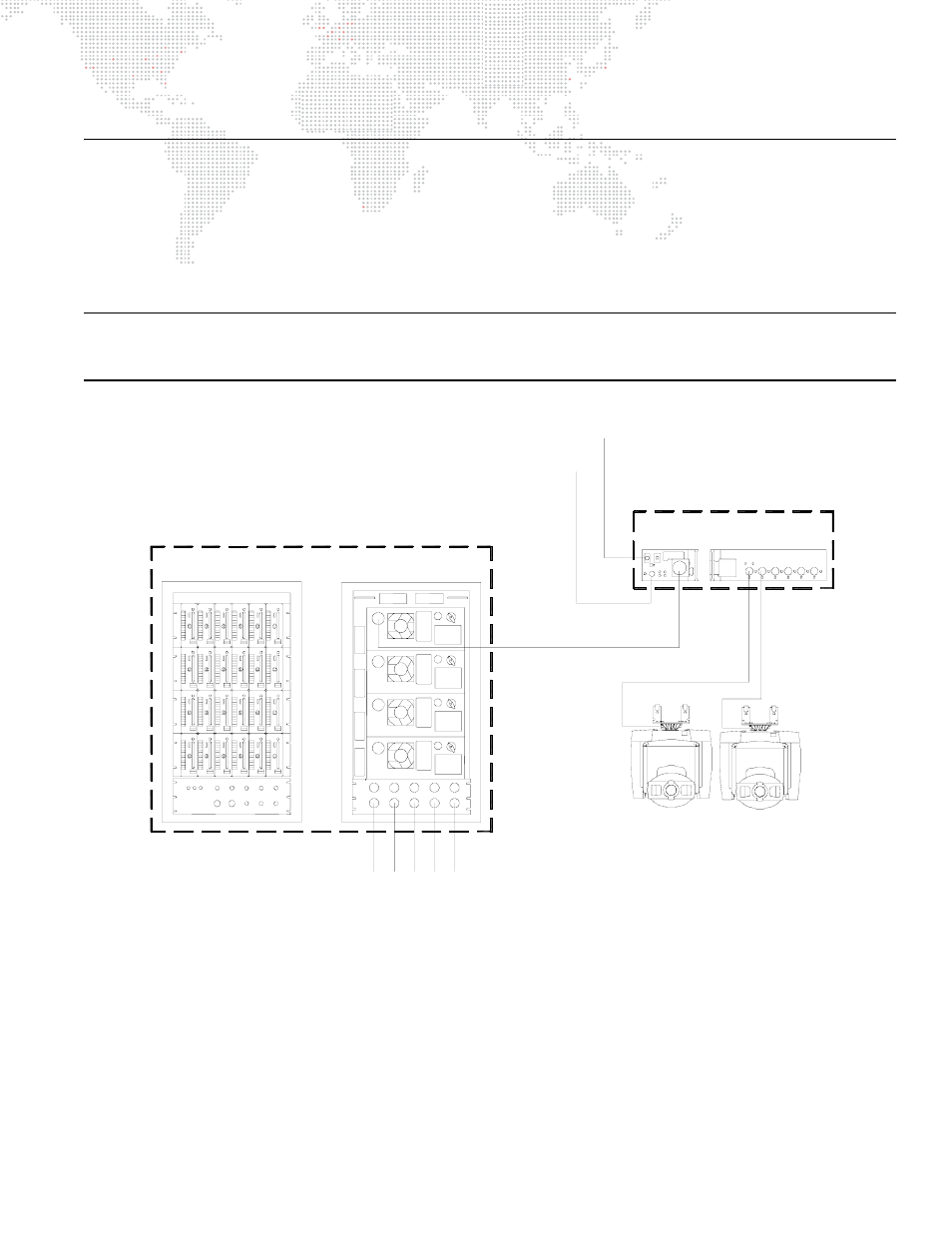
External Power and Data Configuration
Control data signals, 24Vdc, and lamp power are provided by a Series 300 Smart Repeater or Smart Repeater Plus
processing unit to Series 300 luminaires via lamp cables. A maximum of three (3) VL6C+ Luminaires may be powered
from a Smart Repeater unit and a maximum of six (6) VL6C+ Luminaires from a Smart Repeater Plus unit. Lamp power
for VL6C+ Luminaires is provided by APS6 power supply modules located in a Series 300 Modular Rack. The
following diagram shows how data and power are distributed to VL6C+ Luminaires in a sample DMX512 system.
Note: Refer to the VARI
❋
LITE Interface Devices Service Manual (02.5014.0010), VARI
❋
LITE Series 300 Modular
Rack Service Manual (02.9640.0010) and Controlling VARI
❋
LITE Equipment Using a DMX512 Console Manual
(02.3004.0300.52) for more information about the associated equipment.
Figure 1-4: Power and Data Configuration (Typical DMX512 System)
Power Input
VL6C+
VL6C+
Series 300 Smart Repeater
or Smart Repeater Plus Unit *
FRONT
REAR
FRONT
SIDE
Series 300 Lamp Run
(Lamp Power)
A maximum of three (3) VL6C+ Luminaires may be
powered from a Smart Repeater unit and a maximum
of six (6) VL6C+ Luminaires from a Smart Repeater
Plus unit.
Series 300
APS Trunk Cable
*
120/208 Volt
3Ø AC Line
Series 300 Modular Rack
w/ APS6 Power Supply Modules
AC Power
DMX512 From Console