Thermostat wiring, Indoor & outdoor split geothermal comfort systems – Carrier GT-S User Manual
Page 41
Indoor & Outdoor Split
Geothermal Comfort Systems
Carrier Indoor & Outdoor Split Geothermal Heat Pumps - Rev.: 08/10/05
39
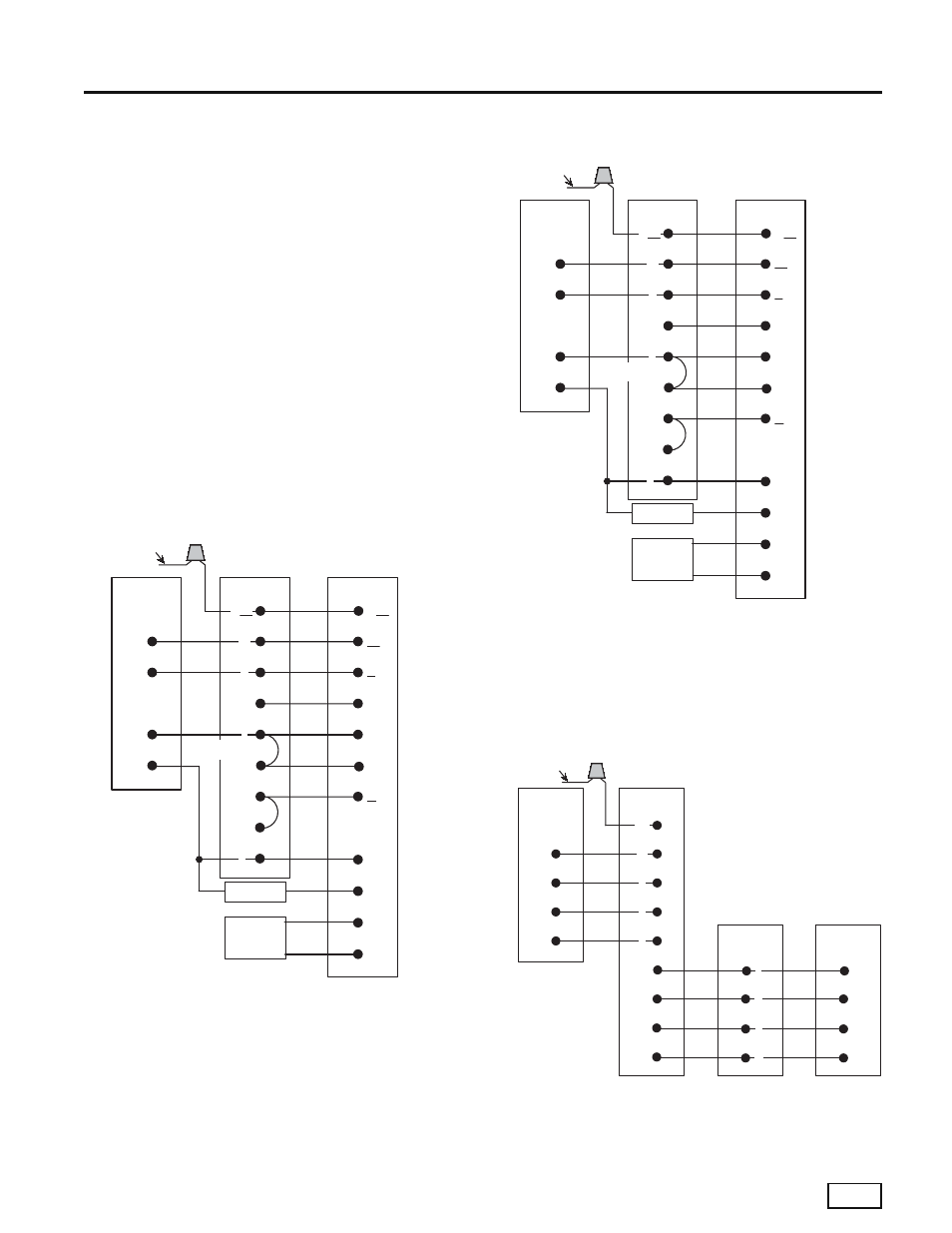
Thermostat Wiring
Thermostat Installation
The thermostat should be located on an interior wall in
a larger room, away from supply duct drafts. DO NOT
locate the thermostat in areas subject to sunlight, drafts
or on external walls. The wire access hole behind the
thermostat may in certain cases need to be sealed to
prevent erroneous temperature measurement. Position
the thermostat back plate against the wall so that it
appears level and so the thermostat wires protrude
through the middle of the back plate. Mark the position
of the back plate mounting holes and drill holes with a
3/16” (5mm) bit. Install supplied anchors and secure
plate to the wall. Thermostat wire must be 18 AWG wire.
Wire the appropriate thermostat as shown in Figures
28a through 28c to the low voltage terminal strip on
the CXM control board. Practically any heat pump
thermostat will work with these units, provided it has the
correct number of heating and cooling stages.
Typical Thermostat Wiring, Single-Stage
Units (2 Heat / 1 Cool)
Typical Thermostat Wiring, Two-Stage Units
(3 Heat / 2 Cool)
Y
O
R
C
Y1/W2
O/W2
G
R
W1
W2
W/W1
FV4
Air Handler
TSTAT CCPRH01
or BBPRH01
CXM Board
(Compressor
Section)
O
G
R
C
Y/Y2
Y1
Y/Y2
From Compressor
Solenoid Valve
Hum
Humidifier
Sol. Vlv. 24VAC
S1
S2
Outdoor
Sensor
DHum
DH
C
Remove Jumper
for Dehum Mode
Notes:
1. Thermostat DIP switches must be configured for two-speed heat pump.
2. Compressor 2nd stage connection is not part of the terminal strip on
the CXM board. A wire nut connection is required between the
compressor solenoid valve and Y/Y2 connection at the fan coil.
Typical Thermostat Wiring,
Infi nity / Evolution Controls
Y
O
C
R
B
Network
Interface Module
FE4 or Other
Communicating
Indoor Unit
CXM Board
(Compressor
Section)
O
R
Y1
Y2
From Compressor
Solenoid Valve
(Notes 1,2)
A
D
Notes:
1. Compressor 2nd stage connection is not part of the terminal strip on
the CXM board. A wire nut connection is required between the
compressor solenoid valve and N.I.M.
2. Y2 connection on N.I.M. is not used for single stage units.
C
C
B
User
Interface
D
A
C
B
D
A
C