Intertek – Oakworks PerformaLift Series User Manual
Page 25
22
MAINTENANCE
& SERVICE
MAINTENANCE & SERVICE
03/14/2013
Report Number: 101033247ATL-0
Issued:
Intertek
IEC 60601-1-2 (Ed.3) Clause 5 (IEC 60601-1-2 (Ed.3) Clause 5)
19.0
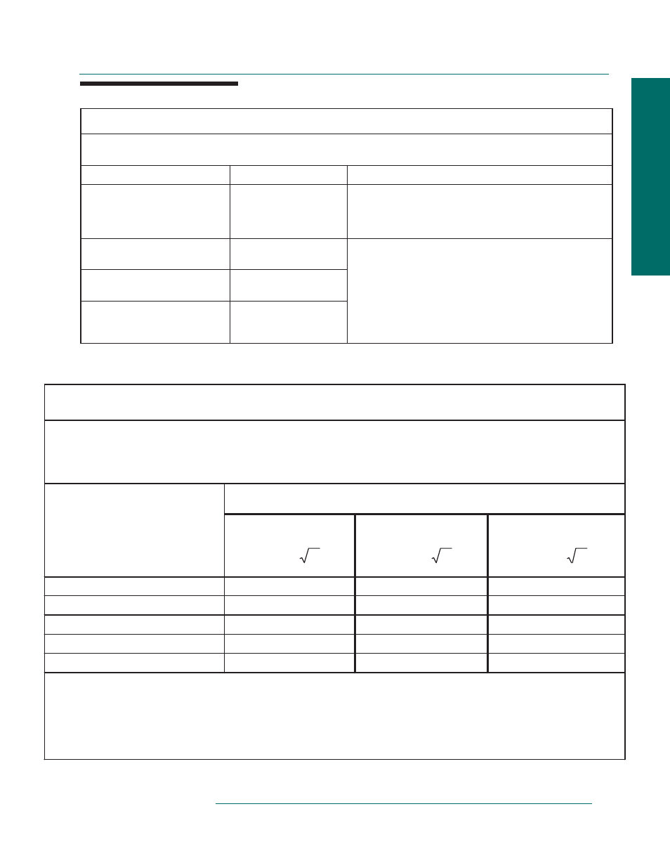
Guidance and manufacturer’s declaration –electromagnetic emissions
The PERFORMALIFT is intended for use in the electromagnetic environment specified below. The customer or the
user of the PERFORMALIFT should assure that it is used in such an environment.
Emissions test
Compliance
Electromagnetic environment – guidance
RF emissions
CISPR 11
Group 1
The PERFORMALIFT uses RF energy only for its internal
function. Therefore, its RF emissions are very low and are
not likely to cause any interference in nearby electronic
equipment.
RF emissions
CISPR 11
Class A
Harmonic emissions
IEC 61000-3-2
Class A
Voltage fluctuations /
flicker emissions
IEC 61000-3-3
Complies
The PERFORMALIFT is suitable for use in all
establishments other than domestic and those directly
connected to the public low-voltage power supply network
that supplies buildings used for domestic purposes.
Table 1
Page 75 of 79
EMC Report for Oakworks Inc. on the Performalift
03/14/2013
Report Number: 101033247ATL-0
Issued:
Intertek
IEC 60601-1-2 (Ed.3) Clause 5 (IEC 60601-1-2 (Ed.3) Clause 5)
19.0
Recommended separation distances
between portable and mobile RF communications equipment and the PERFORMALIFT
The PERFORMALIFT is intended for use in an electromagnetic environment in which radiated RF disturbances are controlled. The
customer or the user of the PERFORMALIFT can help prevent electromagnetic interference by maintaining a minimum distance
between portable and mobile RF communications equipment (transmitters) and the PERFORMALIFT as recommended below,
according to the maximum output power of the communications equipment.
Separation distance according to frequency of transmitter
m
150 kHz to 80 MHz
80 MHz to 800 MHz
800 MHz to 2,5 GHz
Rated maximum output power of
transmitter
W
P
d
2
.
1
P
d
2
.
1
P
d
3
.
2
0,01
0.12
0.12
0.23
0,1
0.38
0.38
0.73
1
1.20
1.20
2.30
10
3.79
3.79
7.27
100
12.00
12.00
23.00
For transmitters rated at a maximum output power not listed above, the recommended separation distance d in metres (m) can be
estimated using the equation applicable to the frequency of the transmitter, where P is the maximum output power rating of the
transmitter in watts (W) according to the transmitter manufacturer.
NOTE 1 At 80 MHz and 800 MHz, the separation distance for the higher frequency range applies.
NOTE 2 These guidelines may not apply in all situations. Electromagnetic propagation is affected by absorption and reflection from
structures, objects and people.
Table 6
Data:
Page 78 of 79
EMC Report for Oakworks Inc. on the Performalift