Maxim Integrated 71M6534 Energy Meter IC Family Software User Manual
Page 71
71M653X Software User’s Guide
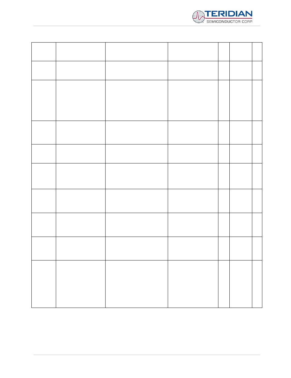
Vmax
Scaling Maximum
Volts for PCB
0.1V
6000
600.0V, from the PCB’s
design.
)9 unsigned 16
ImaxA
Scaling Maximum
Volts for PCB element
A
0.1A
2080
208.0A, from the PCB’s
design.
)A unsigned 16
ppmc1
ADC linear adjust with
temperature
parts per million per degree
centigrade
0
temp_nom, )14, must
be set to a real value
from ]7B before this
can work.
Then it should become
-150
)B signed 16
ppmc2
ADC quadratic adjust
with temperature
parts per million per degree
centigrade squared
0
Should become
-392 after setting
temp_nom
)C signed 16
Pulse 3
source
Source for software
pulse output 3**
Indexed as )7
0
wsum; requires
software pulse module.
)D unsigned 8
Pulse 4
source
Source for software
pulse output 4**
Indexed as )7
4
varsum;
requires software pulse
module.
)E unsigned 8
Scal
Accumulation intervals
of autocalibration**
Count of accumulation
intervals of calibration.
2
2 accumulation
intervals covers both
chop polarities.
)F unsigned 16
Vcal
Volts of
autocalibration**
0.1V rms of AC signal applied
to all elements during
calibration.
2400
240V is a standard full-
scale set-up for meter
test.
)10 unsigned 16
Ical
Amps of
autocalibration**
0.1A rms of AC signal applied
to all elements during
calibration. Power factor must
be 1.
300
30A is a standard full-
scale set-up for meter
test.
)11 unsigned 16
VThrshld
Volts at which to
measure frequency,
zero crossing, etc.
sqrt(v0sqsum)*2
16
88992958
(6531)
75087832 (6533 &
6534)
40V
A real meter should use
sag, but the demo
operates with a power
supply.
)12 unsigned 16
v1.1v1.1
TERIDIAN Proprietary
71 of 116
© Copyright 2005-2008 TERIDIAN Semiconductor Corporation