Maxim Integrated 78Q8430 Software Driver User Manual
Page 18
78Q8430 Software Driver Development Guidelines
UG_8430_004
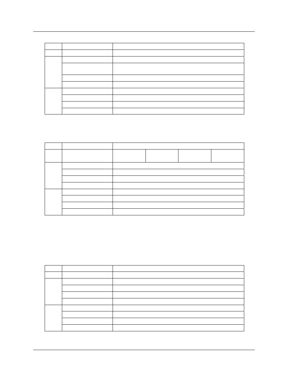
Reg. Field
Value
to
write
CAR ADDR
0x70+N
Data Match
Value of MAC address byte [0]
Data Mask
Value of mask byte [0] from the Wild Card setting (0xFF is
for a perfect match)
Previous Hit Match
0x00 to disable the filter
RMR
Previous Hit Mask
0x00
Byte Offset
Retain default: 0x00
Interrupt
Retain default: 0
Control Logic Action
Retain default: NOP
RCR
Match Control
Retain default: MD
STEP 2: Write address and mask byte [1] through byte [4] to the CAM.
For each byte, the CAM rule indicated by Table 3 based on the filter number, N and byte number is
written as follows:
Reg. Field
Value
to
write
byte [1]:
byte [2]:
byte [3]:
byte [4]:
CAR ADDR
0x68+N 0x58+N 0x50+N 0x40+N
Data Match
Value of MAC address byte [1] … byte [4]
Data Mask
Value of mask byte [1] . . . byte [4]
Previous Hit Match
Value of the CAM rule used by the previous byte
RMR
Previous Hit Mask
0x7F
Byte Offset
Retain default: 0x00
Interrupt
Retain default: 0
Control Logic Action
Retain default: NOP
RCR
Match Control
Retain default: MD
Unlike the settings for byte [0], the RMR Previous Hit Mask field is set to 0x7F and the RMR Previous
Hit Match field is always set to the value of the CAM rule used by the previous byte. For example, the
Previous Hit Mask fields for filter #1 would be 0x71, 0x69, 0x59 and 0x51, for byte [1] through byte [4]
respectively.
STEP 3: Write address and mask byte [5] to the CAM.
Write CAM rule 0x30+N as follows:
Reg. Field
Value
to
write
CAR ADDR
0x30+N
Data Match
Value of MAC address byte [5]
Data Mask
Value of mask byte [5]
Previous Hit Match
Set to the CAM rule that was used for byte [4] (0x40+N).
RMR
Previous Hit Mask
0x7F
Byte Offset
Retain default: 0x00
Interrupt
Retain default: 0
Control Logic Action
Set to TAX
RCR
Match Control
Retain default: MD
18
Rev.
1.0