Wiring the housing board, Figure 19. data connections, Figure 20. video connection – Interlogix UltraView PTZ Dome Series User Manual
Page 30: B a b a
CyberDome II
Installation Manual
22
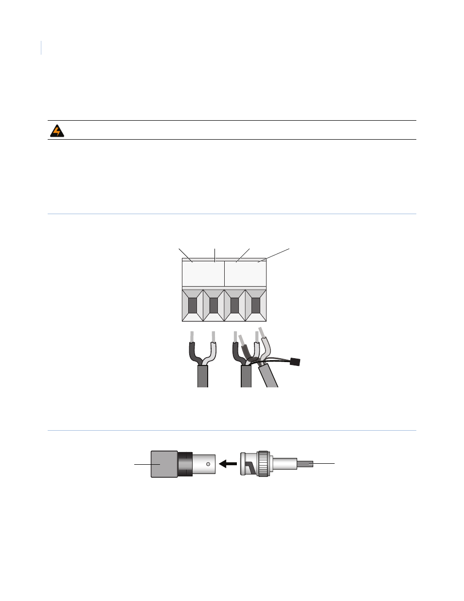
Wiring the housing board
To wire the housing board, do the following:
1. Connect the facility data cables to the main connections, which are the B and A terminals on the
provided 6-pin or 2-pin terminal strip (Figure 19). The main data connections on the terminal strip are
for control wires that are coming in from the keypad. You may also daisy-chain the data signal to
additional domes.
Note: If you are installing RS-485 data, float the shield at the dome and connect it at the keypad.
Figure 19. Data connections
2. Connect the facility video cable (Figure 20).
Note: Use only crimp-on BNC connectors. Do not use screw-on connectors.
Figure 20. Video connection
If you are installing UTP video, use the UTP terminals on the six-pin terminal strip. It provides
connections for UTP video. If you are installing coaxial video, locate the BNC connector.
Note: UTP, which is polarity sensitive, is only available on standard modules with a six-pin connector.
WARNING: Do not run any cables next to the heaters. Doing so could damage the dome or cause an electrical fire.
B A B A
Primary A
RS-485 +
Auxiliary B
RS-485 –
Primary B
RS-485 –
Auxiliary A
RS-485 +
Coaxial video
BNC