IC Realtime PTZ-2801WDR: High Speed PTZ Dome Camera with 28X Zoom User Manual
Page 38
38
7.4 The Problem in Practical Use
There are 120Ωdevice terminal resistance in power socket. There are two connection ways.
The first one is shown as in Figure 7-3. It is the factory default connection method. Now the
jumper caps (connection board) are connected to the second and third socket, the 120Ω has not
connected.
1 2 3
J2
Default jumper setup (120Ω resistance has not connected)
Figure 7-3
If you want to connect to the 120Ω resistance, you can remove the jumper caps from the second
and the third socket and then insert them to the first and second socket respectively. See Figure
7-4. Now you has connected to the 120Ωresistance.
1 2 3
J2
Jumper setup(Connect to 120Ω resistance)
Figure 7-4
7.5 The Problem in Practical Use
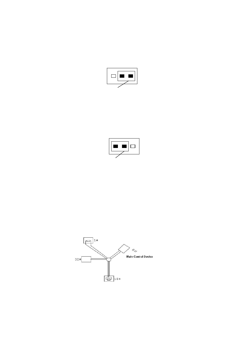
In practical usage, we usually adopt star type connection. The terminal resistance shall connect
to the furthest two devices (Such as device 1# and device 15# in Figure 7-5 ). But this connection
way does not conform to RS485 Bus standard. When the distances between devices are too
long, the signal reflection occurs and anti-jamming decreases, thus the signal reliability becomes
very low. You can see speed dome is not under control or speed dome is running automatically
and can not stop.
Figure 7-5