IC Realtime 4/8/16/32 Channel 2U Network Video Recorder User Manual
Page 25
16
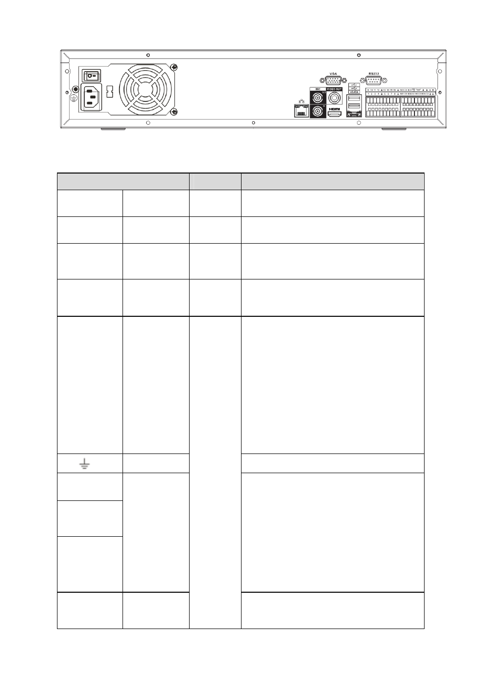
Figure 2-6
Please refer to the following sheet for detailed information.
Port Name
Connection Function
Power button
Power on/off button.
Power input
port
Input AC 220V power.
MIC IN
Audio input
port
Bidirectional talk input port. It is to receive the
analog audio signal output from the devices
such as mike phone, pickup.
MIC OUT
Audio output
port
Audio output port. It is to output the analog
audio signal to the devices such as the sound
box.
1-16 Alarm
input
port 1-16.
There are four groups. The first group
is from port 1 to port 4, the second
group is from port 5 to port 8, the
third group is from 9 to 12, and the
fourth group is from 13 to 16. They
are to receive the signal from the
external alarm source. There are two
types; NO (normal open)/NC (normal
close).
When your alarm input device is
using external power, please make
sure the device and the NVS have
the same ground.
Ground end
Alarm input ground end.
NO1 to NO5
C1 to C5
NC5
5-ch alarm
output port
z
5 groups of alarm output ports. (Group 1:
port NO1~C1,Group 2:port NO2~
C2,Group 3:port NO3~C3, Group 4:port
NO4~C4, Group 5: port NO5, C5,
NC5).Output alarm signal to the alarm
device. Please make sure there is power
to the external alarm device.
z
NO: Normal open alarm output port.
z
C: Alarm output public end.
z
NC: Normal close alarm output port.
A RS485
port
I/O port
RS485_A port. It is the cable A. You can
connect to the control devices such as speed
dome PTZ.