Carrier 50SX024-060 User Manual
Page 3
REQUIRED CLEARANCES TO COMBUSTIBLE MATERIAL — in. (mm)
Unit Top . . . . . . . . . . . . . . . . . . . . . . . . . . . . . . . . 14 (356)
Duct Side of Unit . . . . . . . . . . . . . . . . . . . . . . . . . . . . 2 (51)
Side Opposite Ducts . . . . . . . . . . . . . . . . . . . . . . . . 14 (356)
Bottom of Unit . . . . . . . . . . . . . . . . . . . . . . . . . . . . . . . . . 0
Vertical Discharge First 12 in. (305) of Supply Duct . . . . . . . 1 (25)
NECESSARY REQUIRED CLEARANCES — in. (mm)
Between Units, Control Box Side . . . . . . . . . . . . . . . . 42 (1067)
Unit and Ungrounded Surfaces, Control Box Side . . . . . . 36 (914)
Unit and Block or Concrete Walls and Other Grounded
Surfaces, Control Box Side . . . . . . . . . . . . . . . . . . . 42 (1067)
REQUIRED CLEARANCES FOR SERVICING — in. (mm)
Evaporator Coil Access Side . . . . . . . . . . . . . . . . . . . 30 (762)
Control Box Access Side . . . . . . . . . . . . . . . . . . . . . . 30 (762)
(Except for Necessary Requirements)
Unit Top . . . . . . . . . . . . . . . . . . . . . . . . . . . . . . . . 36 (914)
Side Opposite Ducts . . . . . . . . . . . . . . . . . . . . . . . . 30 (762)
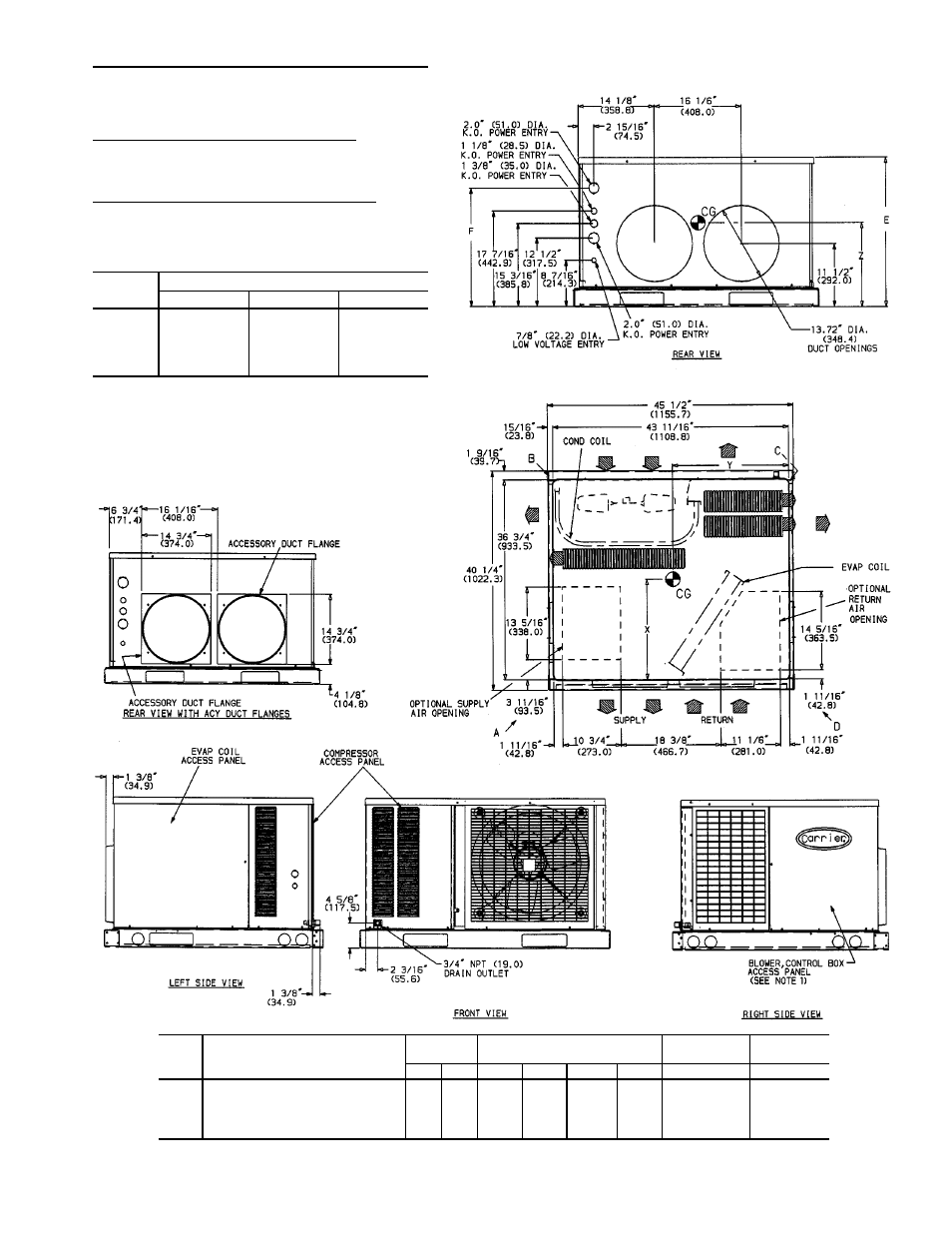
UNIT
50SS
CENTER OF GRAVITY (in./mm)
X
Y
Z
018
19.5/495
21.7/551
12.9/328
024
22.1/562
20.9/532
12.3/313
030
21.8/554
20.4/519
12.3/312
036
21.0/533
20.1/509
12.2/310
042
21.0/532
20.1/510
13.6/344
LEGEND
CG
— Center of Gravity
NEC
— National Electrical Code
COND — Condenser
REQ’D — Required
MAT’L — Material
NOTES:
1. Clearances must be maintained to prevent recirculation of air from
outdoor-fan discharge.
2. Dimensions in (
) are in millimeters.
UNIT
50SS
ELECTRICAL
CHARACTERISTICS
UNIT WT
CORNER WT (Lb/Kg)
UNIT HEIGHT
(in./mm)
DIMENSION
(in./mm)
Lb
Kg
A
B
C
D
E
F
018
208/230-1-60
228
104
66/30
48/22
74/34
40/18
27.4/697
21.5/546
024
208/230-1-60
257
117
65/30
59/27
97/44
36/16
27.4/697
21.5/546
030
208/230-1-60, 208/230-3-60
274
125
66/30
63/29
101/46
44/20
27.4/697
21.5/546
036
208/230-1-60, 208/230-3-60, 460-3-60
290
132
81/37
53/24
114/52
42/19
27.4/697
21.5/546
042
208/230-1-60, 208/230-3-60, 460-3-60
320
146
86/39
62/28
122/55
50/23
31.4/798
25.5/648
Fig. 3 — Dimensions; Units 50SS018-042 with Optional Base Rail
3