Carrier 50SX024-060 User Manual
Page 22
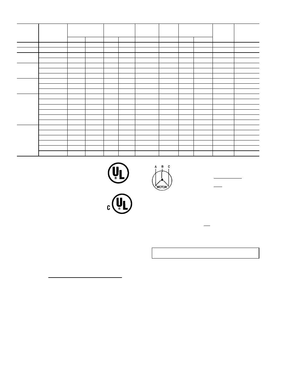
Table 4A — Electrical Data — 50SS Units
UNIT SIZE
50SS
V-PH-Hz
VOLTAGE RANGE
COMPRESSOR
OUTDOOR-
FAN
MOTOR
INDOOR-
FAN
MOTOR
POWER SUPPLY
AWG 60C
MIN WIRE
SIZE
MAX WIRE
LENGTH (ft)
Min
Max
RLA
LRA
FLA
FLA
MCA
MOCP*
018
208/230-1-60
187
253
8.3
45.0
0.7
1.8
12.0
15
14
75
024
208/230-1-60
187
253
12.4
61.0
0.7
2.0
18.2
30
12
80
030
208/230-1-60
187
253
14.4
82.0
1.4
2.3
21.8
30
10
100
208/230-3-60
187
253
9.4
65.5
1.4
2.3
15.5
25
12
80
036
208/230-1-60
187
253
18.0
96.0
1.4
2.8
26.7
40
10
90
208/230-3-60
187
253
11.7
75.0
1.4
2.8
18.8
30
12
65
460-3-60
414
506
5.6
40.0
0.8
1.4
9.2
10
14
100
042
208/230-1-60
187
253
20.4
104.0
1.4
4.0
30.9
50
8
100
208/230-3-60
187
253
14.0
91.0
1.4
4.0
22.9
35
10
85
460-3-60
414
506
6.4
42.0
0.8
2.0
10.8
15
14
100
048
208/230-1-60†
187
253
21.8
124.0
2.1
5.0
40.1
60
6
100
208/230-1-60**
187
253
26.4
129.0
2.1
5.0
40.1
60
6
100
208/230-3-60†
187
253
12.8
93.0
2.1
5.0
23.1
35
10
75
208/230-3-60**
187
253
15.0
99.0
2.1
5.0
25.9
40
10
75
460-3-60†
414
506
16.0
125.0
2.1
6.8
33.0
40
8
90
460-3-60**
414
506
19.3
123.0
2.1
6.8
33.0
50
8
90
060
208/230-1-60†
187
253
28.9
165.0
2.1
6.8
49.0
60
6
100
208/230-1-60**
187
253
32.1
169.0
2.1
6.8
49.0
60
6
100
208/230-3-60†
187
253
6.4
46.5
1.1
2.3
11.4
15
14
100
208/230-3-60**
187
253
8.2
49.5
1.1
2.3
13.7
20
14
100
460-3-60†
414
506
8.0
66.5
1.1
3.2
16.8
20
12
100
460-3-60**
414
506
10.0
62.0
1.1
3.2
16.8
25
12
100
LEGEND
AWG
— American Wire Gage
BRKR — Breaker
CUL
— Canadian Underwriters’ Laboratories
FLA
— Full Load Amps
HACR — Heating, Air Conditioning and
Refrigeration
LRA
— Locked Rotor Amps
MCA
— Minimum Circuit Amps
MOCP — Maximum Overcurrent Protection
NEC
— National Electrical Code
RLA
— Rated Load Amps
*Fuse or HACR Breaker.
†Carrier Scroll Compressor.
**Copeland Scroll Compressor.
NOTES:
1. In compliance with NEC requirements for multimotor and combi-
nation load equipment (refer to NEC Articles 430 and 440), the
overcurrent protective device for the unit shall be fuse or HACR
breaker. The CUL units may be fuse or circuit breaker.
2. Minimum wire size is based on 60 C copper wire. If other than
60 C wire is used, or if length exceeds wire length in table, de-
termine size from NEC.
3. Unbalanced 3-Phase Supply Voltage
Never operate a motor where a phase imbalance in supply volt-
age is greater than 2%. Use the following formula to determine
the percentage of voltage imbalance.
% Voltage Imbalance
max voltage deviation from average voltage
= 100 x
average voltage
EXAMPLE: Supply voltage is 460-3-60.
AB = 452 v
BC = 464 v
AC = 455 v
452 + 464 + 455
Average Voltage =
3
1371
=
3
= 457
Determine maximum deviation from average voltage.
(AB) 457 – 452 = 5 v
(BC) 464 – 457 = 7 v
(AC) 457 – 455 = 2 v
Maximum deviation is 7 v.
Determine percent of voltage imbalance.
7
% Voltage Imbalance = 100 x
457
= 1.53%
This amount of phase imbalance is satisfactory as it is below the
maximum allowable 2%.
IMPORTANT: If the supply voltage phase imbalance is more than 2%,
contact your local electric utility company immediately.
22