Prepare the model for flying – Great Planes RV-4 Park Flyer Kit - GPMA0010 User Manual
Page 32
❏ ❏
18. Insert a wheel into the wheel pant and slide the
wheel pant and wheel onto the landing gear wire. Secure
the wheel to the landing gear wire with a 3/32" [2.4mm]
wheel collar and 4-40 x 1/8" [3.2mm] set screw. Tighten the
set screw so that it will mark the landing gear wire.
❏ ❏
19. Remove the wheel collar, wheel and wheel pant
from the landing gear wire. File a flat spot on the landing
gear wire where the set screw mark is.
❏ ❏
20. Install the wheel pant, wheel and wheel collar back
on the landing gear wire and tighten the set screw. Check
that the wheel spins freely on the wire. With the wheel pant
aligned so that the wheel is centered in the opening, glue
the wheel pant to the landing gear wire with CA. DO NOT
use accelerator as it can weaken the plastic. For a more
secure attachment you can glue a 3/4" [19mm] piece of 1/8"
x 1/4" [3.2 x 6.4mm] balsa to the side of the wheel pant over
the landing gear wire.
❏
21. Return to step 13 and install the left wheel pant.
Note: This section is VERY important and must NOT be
omitted! A model that is not properly balanced will be
unstable and possibly unflyable.
❏
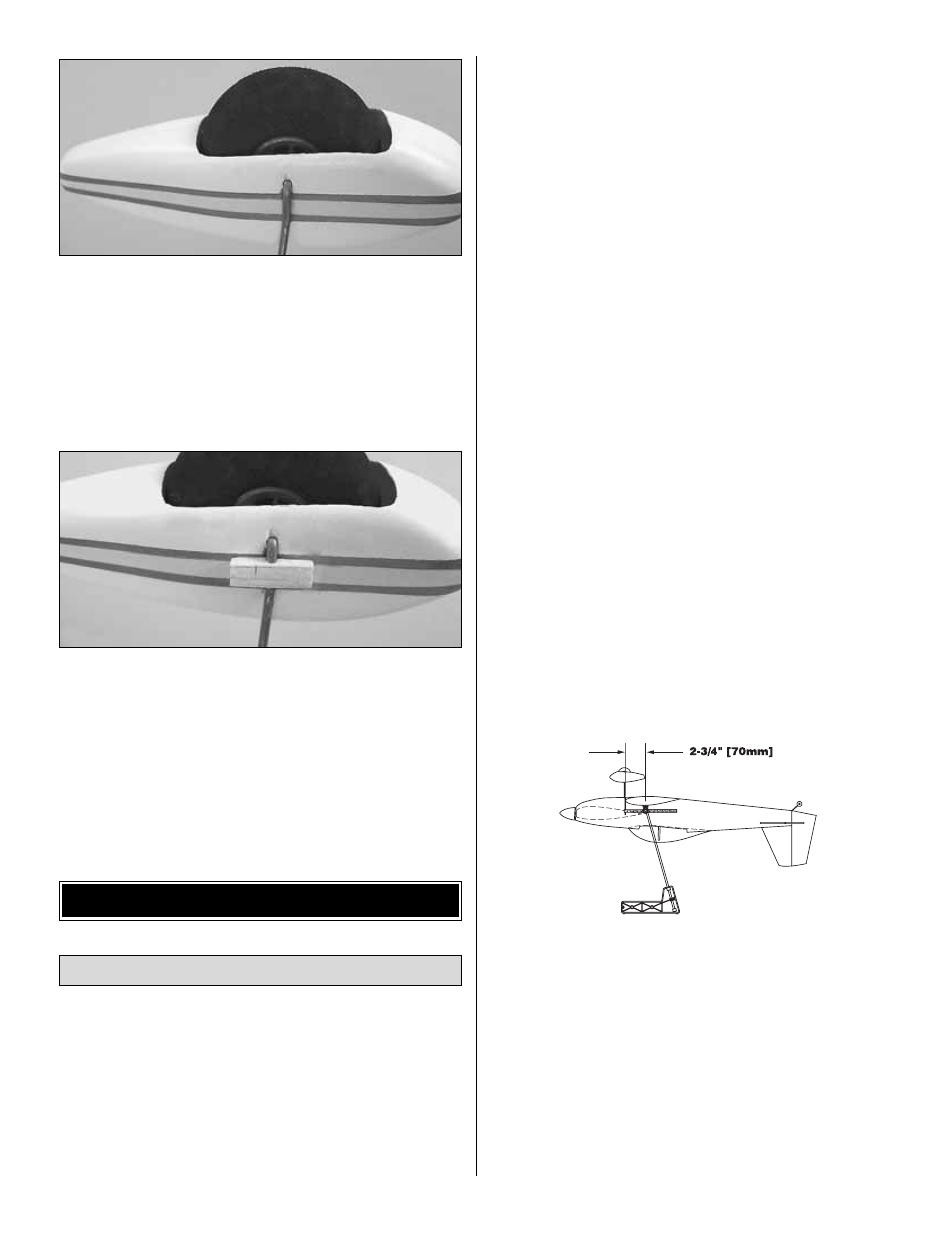
1. Use a fine-point felt-tip pen or 1/8" [3mm] wide striping
tape to accurately mark the balance point on the top of the
wing on both sides of the fuselage. The balance point (C.G.)
is shown on the fuse plan and is located 2-3/4" [70mm] back
from the leading edge of the wing. This is the balance point
at which your model should balance for your first flights.
After the initial trim flights and when you become more
acquainted with the RV-4 Park Flyer, you may wish to
experiment by shifting the balance up to 1/4" [6mm] forward
or 1/2" [12.7mm] backward to change its flying
characteristics. Moving the balance point forward may
improve the smoothness and stability, but the model may
then require more speed for takeoff and may become more
difficult to slow down for landing. Moving the balance point
aft makes the model more agile with a lighter “feel.” In any
case, start at the location we recommend. Do not at any
time balance your model outside the recommended range.
❏
2. Follow the instructions that came with your speed
control to connect the speed control and servos to the
receiver. Temporarily position the receiver inside the fuse and
lay the antenna along the outside of the fuse over the stab.
❏
3. Mount the propeller and spinner to the gear drive using
the prop adapter. If necessary, enlarge the spacer in the prop
with a 3/16" [4.8mm] drill bit or a hobby knife with a #11 blade.
❏
4. Mount the wing to the fuse with two #64 rubber bands
(when it’s time to fly the RV-4 Park Flyer, the wing will be
mounted to the fuse with four #64 rubber bands,
crisscrossing the last two.
❏
5. With the model ready to fly and all parts installed
except for the battery, position the battery pack on the
bottom of the wing. Lift the model at the balance point or
place it on a Great Planes C.G. Machine. If the tail drops, the
model is “tail heavy.” If the nose drops, it is “nose heavy.”
Position the battery on the bottom of the wing so the model
will balance. This is the location where the battery must be
mounted inside the fuselage to balance the model, thus
eliminating additional ballast (nose or tail weight). Because
weight is critical to the flight performance of Park Flyers, it is
best to balance the plane by mounting the battery in the
optimum location. Minor C.G. changes can be made by
changing the location of the receiver as well.
Balance the Model
PREPARE THE MODEL FOR FLYING
32