Great Planes RV-4 Park Flyer Kit - GPMA0010 User Manual
Page 25
❏
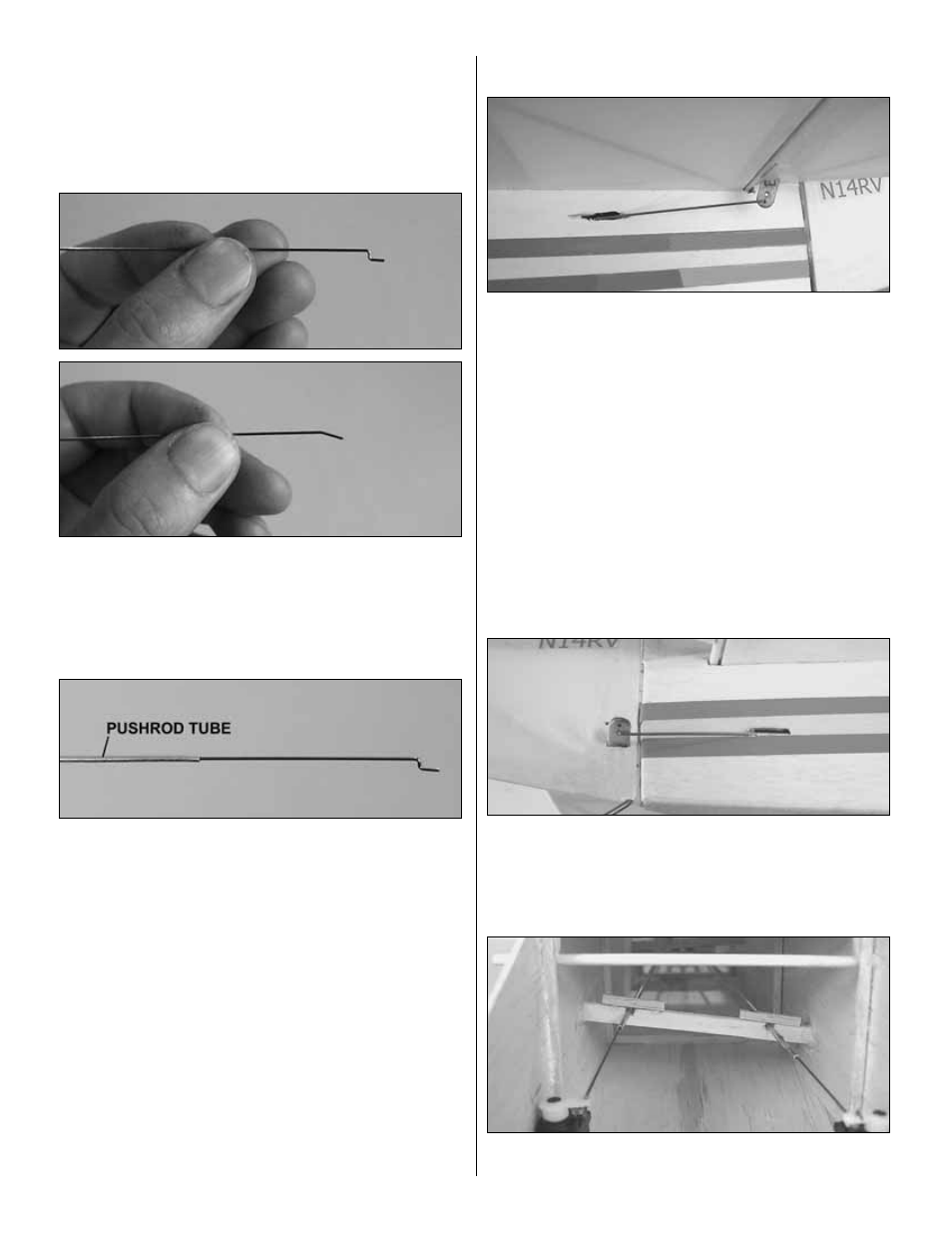
2. Thoroughly clean the remaining .030" x 20" [.76 x
508mm] wire with alcohol or similar solvent, then scuff it with
320-grit sandpaper so glue will adhere.
❏
3. Cut 5" [127mm] from the wire. Make a “Z” bend on one
end and a slight bend on the other end. See the drawing on
the fuselage plan. This is a control horn pushrod end.
❏
4. Use pliers to insert this pushrod end 1" [25.4mm] into
a 1/16" x 12" [1.6 x 305mm] aluminum pushrod tube. Use
thin CA to glue the pushrod end into the pushrod tube.
❏
5. Make another pushrod end from a 4-1/4" [108mm] wire
just the same as the first and insert it into the other end of
the pushrod tube, but do not glue it in. See the drawing on
the fuselage plan. This will be the elevator pushrod.
❏
6. Make sure the pushrod end that is not glued into the
tube fits tightly and will not easily slide in and out. It will be
permanently glued in after the model has been set up and
the exact length of the pushrod has been determined.
Refer to this photo for the following four steps. Note:
The photo shows how the completed installation will look.
❏
7. Cut a slot in the fuselage at the rear of the horizontal
stab for the 1/8" [3.2mm] elevator joiner, installed in the left
elevator. Insert the joiner in the slot and check that the
elevator will move freely once installed. Temporarily hinge
the left elevator to the stab using clear cellophane tape.
❏
8. Insert the elevator pushrod into the fuse through the
slot in the left side. The pushrod end that is not glued into
the tube should be at the servo end.
❏
9. Connect the front of the pushrod to the servo arm, then
mount the servo arm to the elevator servo. Connect the other
end of the pushrod to the outer hole in the elevator control horn,
then insert the control horn into the slot in the elevator.
❏
10. Slide the pushrod end in or out of the pushrod tube
until the elevator is centered when the servo is centered.
❏
11. Make the rudder pushrod and join the rudder to the
fin the same way. The rudder pushrod should be inserted
into the inner hole of the rudder control horn.
Note: The photo shows how the completed installation will look.
❏
12. The pushrods should be braced at the locations
shown on the plan. This photo shows the bracing installed
25