Great Planes CAP 232 1.60 ARF - GPMA1410 User Manual
Page 22
❏
3. Remove the template and enlarge the holes using a
1/4" [6 mm] drill bit.
❏
4. Mix a small amount of 30-minute epoxy. Apply a few
dabs of epoxy to the front of four 10-32 or 1/4" blind nuts (not
included). Hold the blind nut against the back of the firewall
and thread a 10-32 or 1/4" bolt (not included) with a washer
into the blind nut. Tighten the bolt to draw the blind nut into
the wood. Be careful to avoid getting excess epoxy into the
threads on the blind nuts.
❏
5. Mount the engine to the firewall so that the distance
from the firewall to the drive washer is 7-1/4" [184 mm].
❏
6. Mount the electronic ignition unit as shown.
❏
7. Following the guidelines in the shaded box previously
shown, install an ignition kill switch into the fuselage.
❏
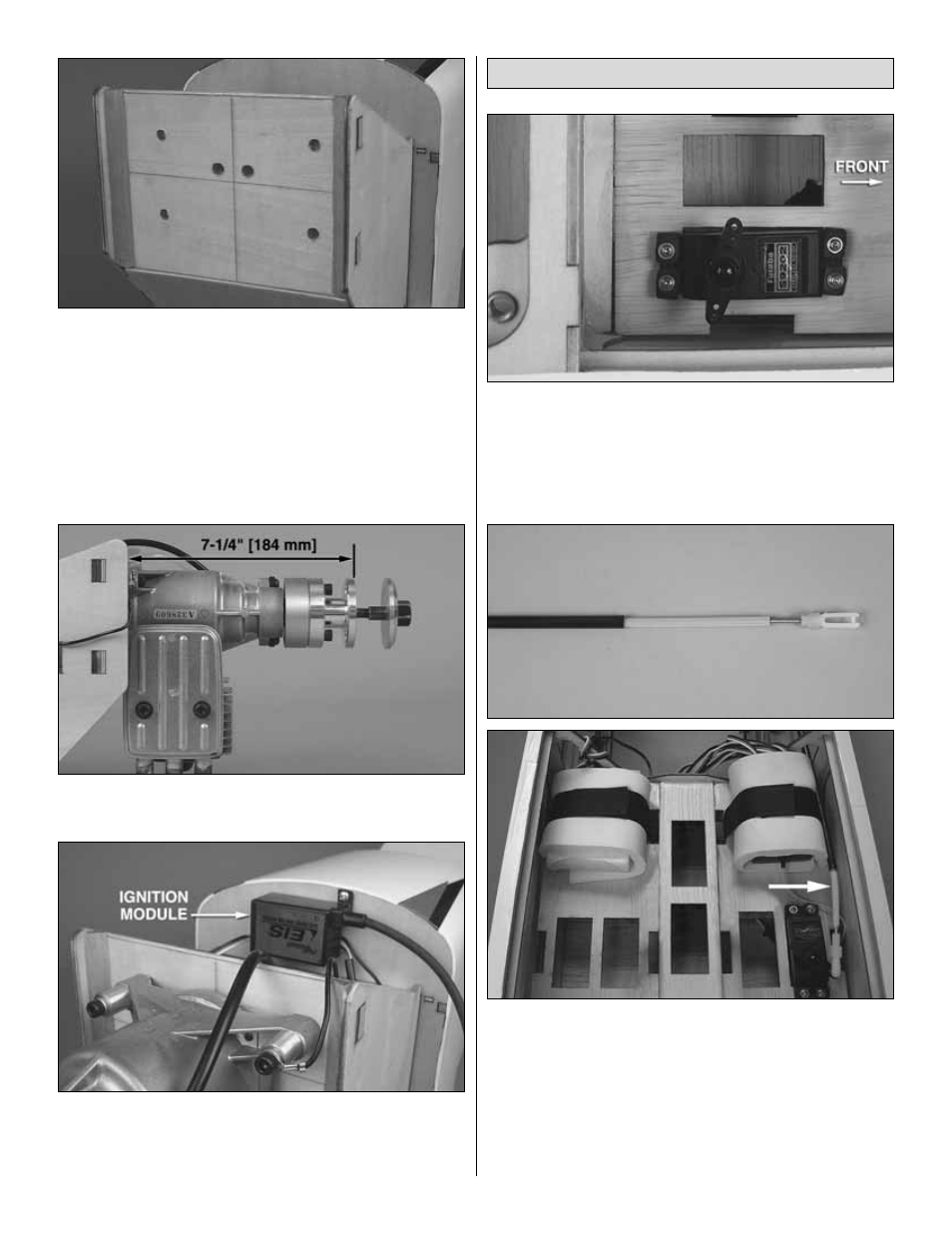
1. Install the throttle servo into the servo tray using the
hardware provided by your servo’s manufacturer. Choose
the mounting position that gives you the most direct route to
your carburetor. For the Fuji-Imvac 43cc gas engine,
typically the servo location would be in the far right mounting
position as shown.
❏
2. Using a non-metallic flexible pushrod system, connect the
throttle servo to the carburetor on your engine. Shown in the
photo is the Semi-Flexible Pushrod system from Great Planes
(GPMQ3714). This system comes with ideal components for
this type of throttle connection. Since engine installations can
vary, the location of the holes in the formers and firewall for the
pushrod to route through will also vary. For our installation of the
Fuji-Imvac 43cc gas engine, the throttle pushrod was routed
along the right side of the fuselage as shown.
Install the Throttle Servo (Gas Engine)
22