Great Planes CAP 232 1.60 ARF - GPMA1410 User Manual
Page 16
❏
16. Hold two ends of the pull-pull cable together, making
sure they are even. Cut the cable at the midpoint to create
two equal lengths. Route the non-threaded end of the cable
through the hole in the rear of the fuselage. Pull the cable
through the fuselage to the rudder servos.
❏
17. Assemble one end of each half of the cable as shown
in the sketches above. Each clevis should be threaded
halfway onto the coupler. Do not crimp the swage fitting yet
as it will need to slip for adjustments.
❏
18. Attach the clevis end of the cable to the 3rd hole out
on the rudder control horns and route the unassembled end
of the cable into the fuselage through the teardrop shaped
holes in the tail. Pull the cable forward to the rudder servos.
❏
19. Assemble the remaining end of the cable as you
did before.
❏
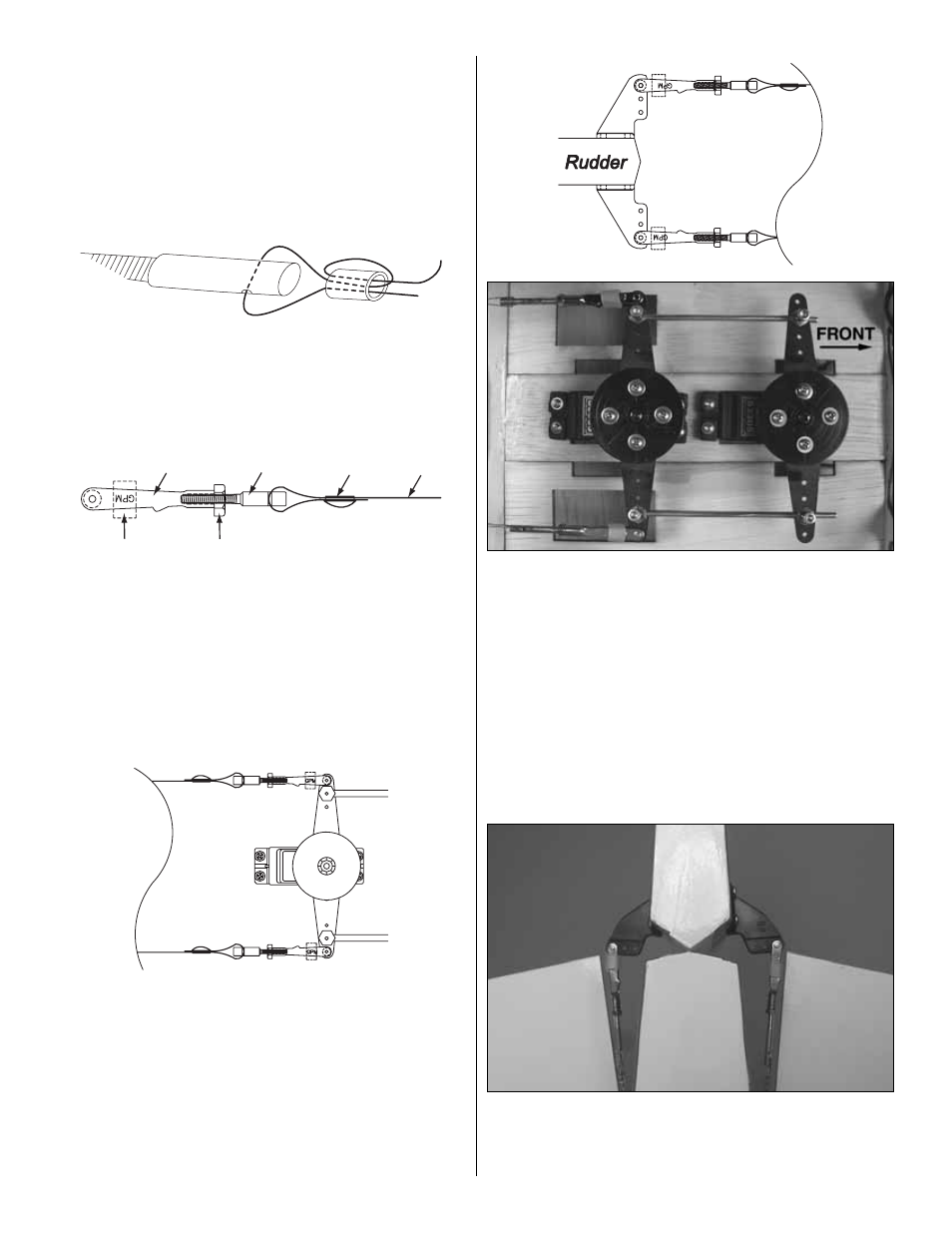
20. Connect the pull-pull cables to the aft rudder servo
arm extension as shown.
❏
21. Once both cables are installed, turn on your radio and
center the servo arms. Center the rudder.
❏
22. With the radio still on and the rudder centered, pull the
slack from each cable at the clevises. Do not pull the cables
too tight. A slight amount of slack is acceptable.
❏
23. When satisfied with the cable tension, crimp the
swage fitting securely in place using pliers. This will secure
the cable length.
❏
24. Fine tuning of the cable tension can be performed by
adjusting the clevis on the coupler. When done adjusting the
tension, secure the clevis by tightening the nut against the clevis.
Be sure to apply a drop of thread locker to hold the nut in place.
Clevis
Swage
Cable
Clevis
Retainer
Nut
Threaded
Coupler
16